


RC module
Description: An RC circuit is used to introduce time delay in circuits. A combination of resistor and capacitor gives a time constant.
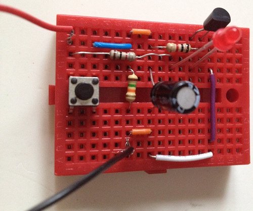
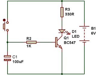
The following circuit shows a basic RC circuit. In the figure C1(100uF) works as a storage capacitor. When you press the switch, the capacitor charges quickly and provides base current to the transistor Q1, that results in collector current and that glows the LED D1.. The resistance R2(1K) provides a time constant of around 10seconds. After 10seconds, the base current is not enough for driving the transistor, so the LED also goes off.
The time constant of an RC network is the time required for the capacitor to reach 63% of its maximum possible voltage. The time constant formula is:
T= RxC
T= 1kOhm x 100uF
T= 0.1second.
If the capacitor is 1000uF, then the time constant would be 1 second. READ MORE ABOUT RC CIRCUIT.
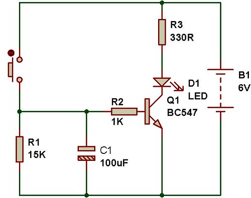
In the second circuit, there is another resistor connected to capacitor. This resistor helps the capacitor to discharge quickly. In absence of this resistor, you will see faint light for a long time. In order to avoid that faint light, we use resistor R1 in all the MINIBREAD projects.

WATCH THE VIDEO:

This work is licensed under a Creative Commons Attribution-NonCommercial 3.0 Unported License.
🛠️ Dive into our collection of DIY Kits, 🔊 Audio Amplifiers, Digital Scoreboards, FM transmitters, and more!
🎶 Explore endless possibilities at our new store.


Hi Sir,
can i operate TSOP1738 infrared reciver (Description of remote operated switch) by above circuit.
iwanna operate above infarred recever by my own infrared transmeter.(witout tv,remote)