


Basic RC circuit
Basic RC circuit
Using an RC circuit, we can keep an LED on for specific time as determined by resistors R1, R2 and capacitor C1.
As we press the Push-to-On switch, the capacitor C1-1000uF gets charged and it gives biasing voltage to the transistor Q1 through resistance R2-1K. As we leave the switch, the LED keeps on glowing because of the charge present in the capacitor. Discharging rate of capacitor is determined by the resistor R1 and R2, hence it also determines the timing of RC circuit. The charge in the capacitor discharges through R1 and R2.
Click here to read about RC circuit.

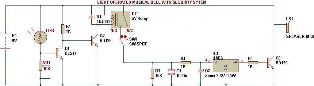
Light operated musical bell with security system
For the circuit to work as light operated musical bell, we need to connect the SW1- switch to N/C terminal of relay. LDR has to be kept in a dark case. Since LDR is kept in dark, the relay remains active all the time. So, pole of relay remains connected to N/O terminal all the time. This configuration does not provide any power to the RC circuit. When we put light on the LDR(using a pointed source of light, e.g. Laser torch), the relay gets deactivated and RC circuit gets power through the pole of relay. This makes the circuit play music for a specific time.
Light operated security system
For the circuit to work as a security system, we need to connect the SW1- switch to N/O terminal of relay. LDR has to be kept in a dark case, but there should a pointed light (e.g. laser torch) always falling on the LDR. Since there will be light all the time, relay remains inactive all the time. This configuration does not provide any power to the RC circuit. When someone blocks the light falling on LDR, the relay gets activated and RC circuit gets power through the pole of relay.
This makes the circuit play music for a specific time as determined by the values of resistors R3 and capacitor C1.The above has been made combining the logic of a dark detector and a musical circuit(using UM66).
![]()


![]()

🛠️ Dive into our collection of DIY Kits, 🔊 Audio Amplifiers, Digital Scoreboards, FM transmitters, and more!
🎶 Explore endless possibilities at our new store.


Could you send me the working mechanism of the circuit in description?