


Serial LCD do-it-yourself(DIY) kit
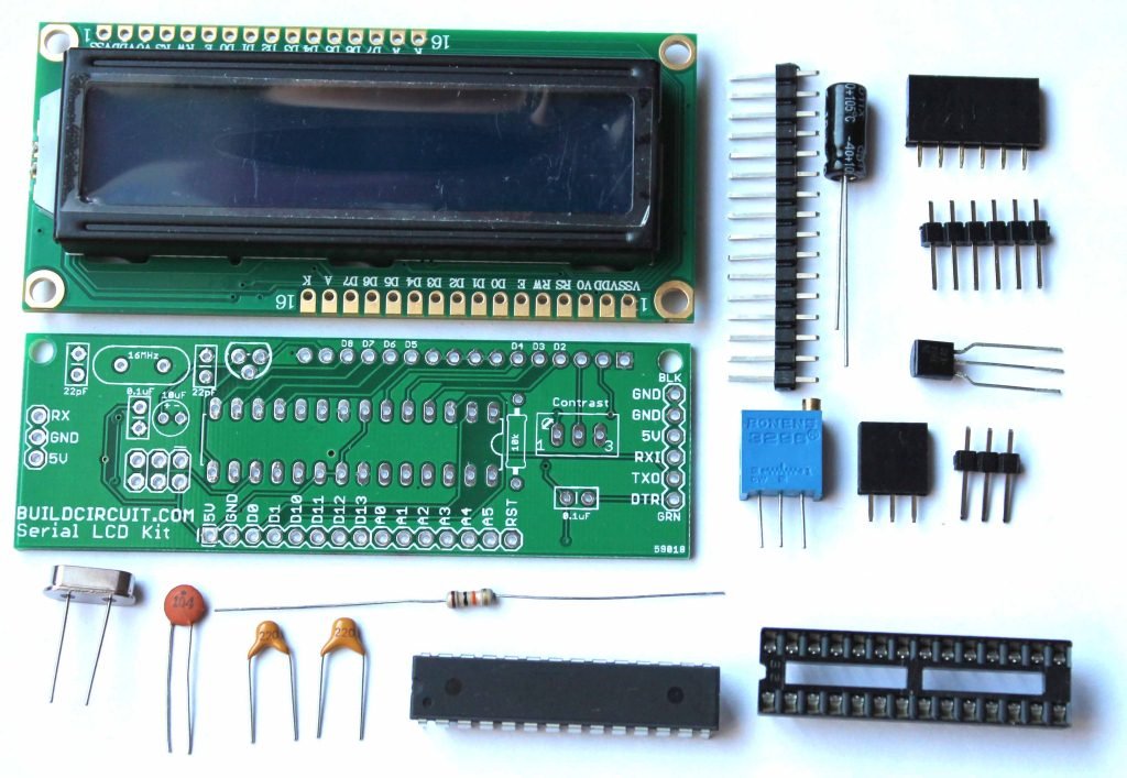
This is a simple serial lcd do-it-yourself (DIY) kit based on Arduino. I derived this kit from the open source eagle file available on sparkfun.com. The only difference is that I used low cost components to make it more affordable. It uses the libraries and examples published on the quickstart page of sparkfun.
 This kit allows you to display all kinds of texts and numbers using only two digital pins of Arduino. You know that LCDs can be difficult to use because usually we use 6 digital pins to connect it with Arduino, so this kit includes an embedded processor (Arduino based) that does the hard work for you. This LCD is easy to connect to any 5V microprocessor that has a serial port, such as an Arduino, AVR, PIC, etc. However, this tutorials shows its connection with the Arduino based microcontroller only.
There are only three connections you need to make to the LCD:
RX (receive): Serial receive (input to the display). 5V TTL level, 9600 baud (default rate, can be changed), 8 bits, 1 stop, no parity.
GND (ground): Ground for the power supply. Black
5V (power): Power supply, this should be +5V at up to 60mA if the back light is fully on.
The kit comes with 3-pin male and female headers for connecting the RX, 5V and GND to the Arduino board. If you fix a male header, you need a 3-pin jumper connector wire and if you fix a female header, normal wire meant for breadboard experiments can be used.

- 3 pin jumper wire
(Tip: If you want to connect the display to a breadboard, tin the ends of the wires to make them easier to insert into the breadboard holes. To tin wire, strip about 1/4″, and put some solder on the bare wire to make it stiffer).
Note that the RX input should be a 5V TTL-level signal directly from a 5V microcontroller or other 5V system. You should NOT connect the board to RS232-level voltages, which are +/-10V and will damage the board (see our explanation here). If you do wish to connect this display to RS232 signals, you can use a level-shifting board such as a PRT-00449 to translate the RS232 signals to TTL-level signals.
Using the display
As I already stated that I have used libraries of Sparkfun, when you power up the board, you’ll briefly see a SparkFun splash screen, and then the display will go blank. To send text to the board, wait 1/2 second (500ms) after power up for the splash screen to clear, then send text to the display through your serial port. The display understands all of the standard ASCII characters (upper and lowercase text, numbers, and punctuation), plus a number of graphic symbols and Japanese characters. See the HD44780 datasheet for the full list of supported characters.
If you send data that goes past the end of the first line, it will skip to the start of the second line. If you go past the end of the second line, the display will jump back up to the beginning of the first line. (Tip: you can simulate a scrolling window in software by copying the second line to the first line, and clearing the second line.)
Note that the Arduino and other systems with bootloaders may send “garbage” characters to the display while the system is starting up or being reprogrammed. To avoid this, you can use a software serial library to create a separate serial port from the USB port, as in the following examples.
LCD FIRMWARE: First of all, upload this code to the ATmega328p chip of your serial LCD kit. Then, test any of the sketches given below:
NOTE that these examples were written for Arduino 1.0 and later. If you are using an older version of Arduino, you can download the older examples here: serial_lcd_quickstart_Arduino02.zip.
You can copy and paste these sketches into your Arduino 1.0 (or later) editing window, or download them here: serial_lcd_quickstart_Arduino10.zip.
More information
Other commands are available to change the backlight level, turn the splash screen on and off (and customize it to your own text) , change the baud rate, etc. See the LCD datasheet for information on all the available commands. For a more extensive example sketch that shows you how to create a scrolling marquee, create a timer, display sensor data and control the backlight, download the following examples: SerLCD Arduino example – Arduino 0023 and earlier SerLCD Arduino example – Arduino 1.0.2 and later . Alternatively, you can use the SerLCD libary found on the Arduino website. If you are using Linux, you may want to try this library instead.
Tips and troubleshooting
If the display is powered up without the RX line connected to anything, the display may fill with strange characters. This is because the display is receiving random noise on the disconnected line. If you connect the RX line to a true TX port, this will not happen. If the display is unreadable or washed out, the contrast may need to be adjusted. Send some text to the display ( see: the first example sketch above), then use a miniature Phillips screwdriver to gently turn the contrast 10k trimpot labeled ‘contrast’ on the PCB of the kit until the text is as clear as possible ( please be gentle with the trimpot ).
This display also has a back-light that can be adjusted for best readability, see the LCD datasheet for information. This display has a feature where if the display receives a CTRL-R character during its half-second splash screen display, it will temporarily revert to 9600 baud until power is cycled. This is to allow you to regain control of the display if you set it to an unknown baud rate. Some systems like Arduino send bootloader information out the serial port when the system starts up, which can fool the LCD into this recovery mode. If this is a problem, there are a few solutions: you can use a different pin and the NewSoftSerial library to create a TX port that doesn’t get used during startup (as shown in the example sketches above), or leave the display at the default 9600 baud rate, and clear the display when your program starts.
Modification by BuildCircuit- For novices and amateurs
Upload this sketch on to the ATmega328p microcontroller of the display. Use a FT232RL breakout board for uploading the sketch. Optional links: Serial_LCD_Kit . Then, upload the following code to your Arduino board. When you type texts on the serial monitor, the texts will be displayed on the LCD.

Checkout this tutorial: How to assemble serial LCD kit
Serial LCD firmware– Use FTDI breakout board to upload the firmware to your ATmega328p chip of your kit.
Upload the following sketch to your Arduino:
Resources:
- Serial LCD Kit Schematic
- Serial LCD Kit Firmware (github)
- Serial LCD Kit Command List (github wiki)
- NewSoftSerial Library – Required for the example sketches. Sets up a second (third, fourth,…) serial port on the Arduino.
- Serial LCD Kit Passthrough Example Sketch – Send any character from the Arduino’s serial monitor to the LCD.
- Serial LCD Clock Example Sketch – Displays a digital clock on the Serial LCD. This is a good example of how to use special commands, like clear, with the display.
- Eagle File- Modified by BuildCircuit- Download
- Eagle Fie- Original
🛠️ Dive into our collection of DIY Kits, 🔊 Audio Amplifiers, Digital Scoreboards, FM transmitters, and more!
🎶 Explore endless possibilities at our new store.


I
how do i buy your products
You can buy it on minibread.com. The webstore is also owned and operated by me.