Digital object counter kit- Assembly tutorial
This article is about assembly of counter module used with digital object counter DIY kit. If you have come to this page directly from a search engine, please visit this page first to know about digital object counter. The suggested page gives you more details about this kit. You will eventually come back to this page, don’t worry 🙂 .
This kit includes everything you need to make a simple digital object counter. The object counter kit set includes an infrared (IR) transmitter DIY kit to make it work. The counter module and the infrared transmitter module can be kept at a distance of 1 meter with infrared LED facing towards the infrared sensor. Â The LED continuously transmits infrared rays to the sensor and whenever an object obstructs the rays, the ‘seven segment display’ counts from 0 to 99.
Assembly of digital object counter is very straightforward and all components are through-hole. You can see the label and images printed on the circuit board and assemble the components accordingly.
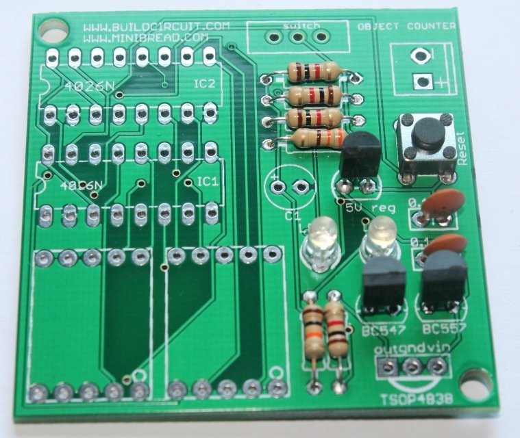
Check the PCB of the counter kit:
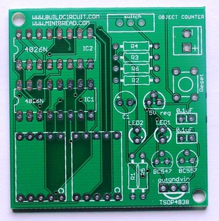
You can notice on the PCB that the component names have been labeled clearly. You can also check all the assembly images from flickr.com.
Step 1: Fix all the resistors.
Values are as follows:
a. R1: 10 kilo Ohm: Brown- Black- Orange
b. R2: 330 Ohm: Orange- Orange- Brown
c. R3, R4, R5 and R6: 1 Kilo Ohm- Brown- Black- Red
Step 2: Fix 0.1uF ceramic capacitors. The code for 0.1uF capacitor is 104. You can check other capacitor codes from this site.
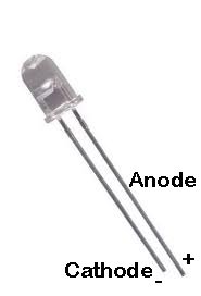
Step 3: Fix 2 pcs of 3mm LEDs. Insert the long pin(Anode +) in the hole marked + and insert the other short pin(cathode -) in the hole marked – .
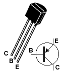
Step 4: Fix BC547 NPN transistor.
Step 5: Fix BC557 PNP transistor.
Step 6: Fix 5V regulator chip(7805). Download datasheet
Step 7: Fix reset switch. Reset switch resets the counter and set it to 0.
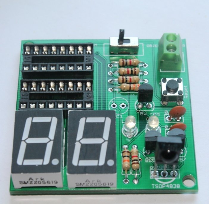
Step 8: Fix 2pcs of 16-pin DIL sockets and screw terminal.
Step 9: Fix SPDT switch.
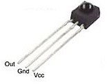
Step 10: Fix 2pcs of seven segment display and TSOP4838 infrared receiver. The kit uses common cathode displays.
Step 11: Fix 100uF electrolytic capacitor.
Step 12: Connect a 9V battery.
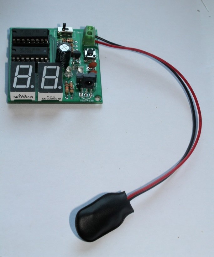
Your counter module can be tested with a general remote control. As you press the remote control, the number on the display increases.
To use the module as an object counter, you need to assemble IR transmitter module also. Please click here for assembly instructions of infrared transmitter.
Other related tutorials:
-
3 Digit Digital Object Counter ASSEMBLED Kit With Infrared Transmitter And Laser Module
US $14.95Read more3 Digit Digital Object Counter ASSEMBLED Kit With Infrared Transmitter And Laser Module
US $14.95This is 3 digits digital object counter kit for electronics beginners and hobbyists. It is the upgraded version of our previous 2 digits and 3 digits object counter.
You can use this 3 digits digital object counter for counting objects or people entering in a room. It can be used by engineers for learning about digital counters.
This DIY digital object counter works with VS1838 infrared receiver and photoresistor and there are three seven segment displays displaying numbers from 0 to 999. An IR transmitter is directed towards the VS1838 infrared receiver of the counter module and objects are moved between the two modules. Each time an object passes between the two modules, the seven-segment displays show increment in numbers from 0 to 999.
Out of stock
Quick View
Check out all the counters
-
1.8″ Photoresistor And Laser Operated Medium Digital Objects Counter
US $24.95Add to cartQuick View -
2.3″ Common Anode Seven Segment Display Driver
US $19.95Add to cart2.3″ Common Anode Seven Segment Display Driver
US $19.95- This is a 74LS192 based up and down counter driver module for driving 2.3″ seven-segment display. The module has headers on two sides to receive up/down count signals and to concatenate with another driver module. You can concatenate unlimited displays.
- The module can be triggered with NE555, flashing LED, Scoreduino-A, basic trigger module, and Arduino. It can also be triggered by anything that generates a clock pulse.
- It works ‘strictly’ with 9V power supply. Do not exceed more than 9V.
9 in stock
Quick View -
2.3″ common cathode seven segment display driver
US $11.95 – US $12.95Select options2.3″ common cathode seven segment display driver
US $11.95 – US $12.95This is a CD4026 based up counter driver module for driving 2.3 inches common cathode seven segment display. The module has headers on two sides to receive up count signals and to concatenate with another driver module.
The module can be triggered with NE555, flashing LED, and Arduino. It can also be triggered by anything that generates a clock pulse.
Quick View -
CD4026- 1 Digit Up Counter Module
US $4.95Add to cartCD4026- 1 Digit Up Counter Module
US $4.95- It works as an UP counter. You can instantly test the up count of the display using a flashing LED.
- It is a handy tester for 0.56″ seven segments common cathode display.
- Works with Arduino or NE55 or whatever that gives pulse.
- You can concatenate as many displays as you want.
- With this, you can build your own digital objects counter.
- Size: 15mmx49mm
50 in stock
Quick View -
CD4029 Based Up And Down Counter For Arduino And NE555
US $7.95Add to cartQuick View -
Photoresistor And Laser Operated Large Digital Objects Counter With 2.3″ Displays
US $29.95Add to cartPhotoresistor And Laser Operated Large Digital Objects Counter With 2.3″ Displays
US $29.95A laser light module illuminates the photoresistor continuously and whenever any object obstructs the laser light falling on the photoresistor, the counter increases the count. You can use this 3 digit digital objects counter for counting objects or people entering a room. It can be used by engineers for learning about digital counters.
4 in stock
Quick View