RC module

Description: An RC circuit is used to introduce time delay in circuits. A combination of resistor and capacitor gives a time constant.

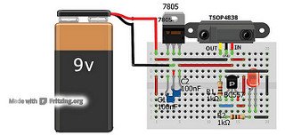
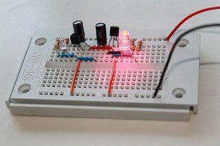
The following circuit shows a basic RC circuit. In the figure C1(100uF) works as a storage capacitor. When you press the switch, the capacitor charges quickly and provides base current to the transistor Q1, that results in collector current and that glows the LED D1.. The resistance R2(1K) provides a time constant of around 10seconds. After 10seconds, the base current is not enough for driving the transistor, so the LED also goes off. (more…)

Multivibrator module

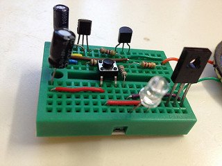
Description: A multivibrator has identical components(capacitors, transistors and resistors) arranged on the left and right hand sides that can be used to implement a variety of simple two-state systems such as oscillators, timers and flip-flops. In a multivibrator circuit, increasing the value of the two electrolytic capacitors increases the time each LED remains on/off.  (more…)

Basic RC circuit

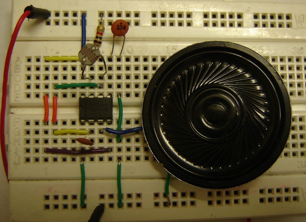
For the circuit to work as light operated musical bell, we need to connect the SW1- switch to N/C terminal of relay. LDR has to be kept in a dark case.

Mode of NE555- Astable

This circuit has been configured in Astable mode. The output pulses are determined by the values of resistors R1, R2 and the timing capacitor C1. The formula for the frequency of pulses is: f= 1.44/[(R1+2R2)*C1].

Sound generator and Musical toy organ

One of the main objectives of LDR Engineering projects is to make students capable of developing their own logic for making devices. Here is an example that tells how LDR Engineering helps in developing ideas.

Search for products

Back to Top
Product has been added to your cart