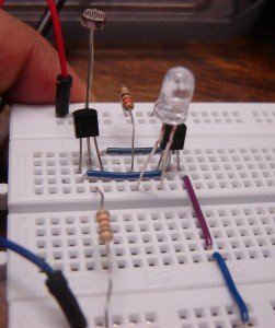
Dark sensor on breadboard

The circuit is ready for testing. Connect battery terminals and see the output. As you block light falling on LDR(Light dependent resistor), the LED glows.

OUTPUT:

[youtube]http://www.youtube.com/watch?v=qmWAgoHwy3w[/youtube]

THIS CIRCUIT IS EXTREMELY SENSITIVE TO DARKNESS. EXPERIMENT THE CIRCUIT IN A HIGHLY ILLUMINATED ROOM.

LED GLOWS EVEN IN LESS DARKNESS. Use torch light if the LED glows in less darkness. You can adjust the sensitivity of the circuit using a variable resistor in place of R3-300Ohm. Try this circuit with other resistances as well, for example, 1K, 10K and 100K, etc.

The simplest and the cheapest FM transmitter- Do-it-yourself(DIY) kit for amateurs

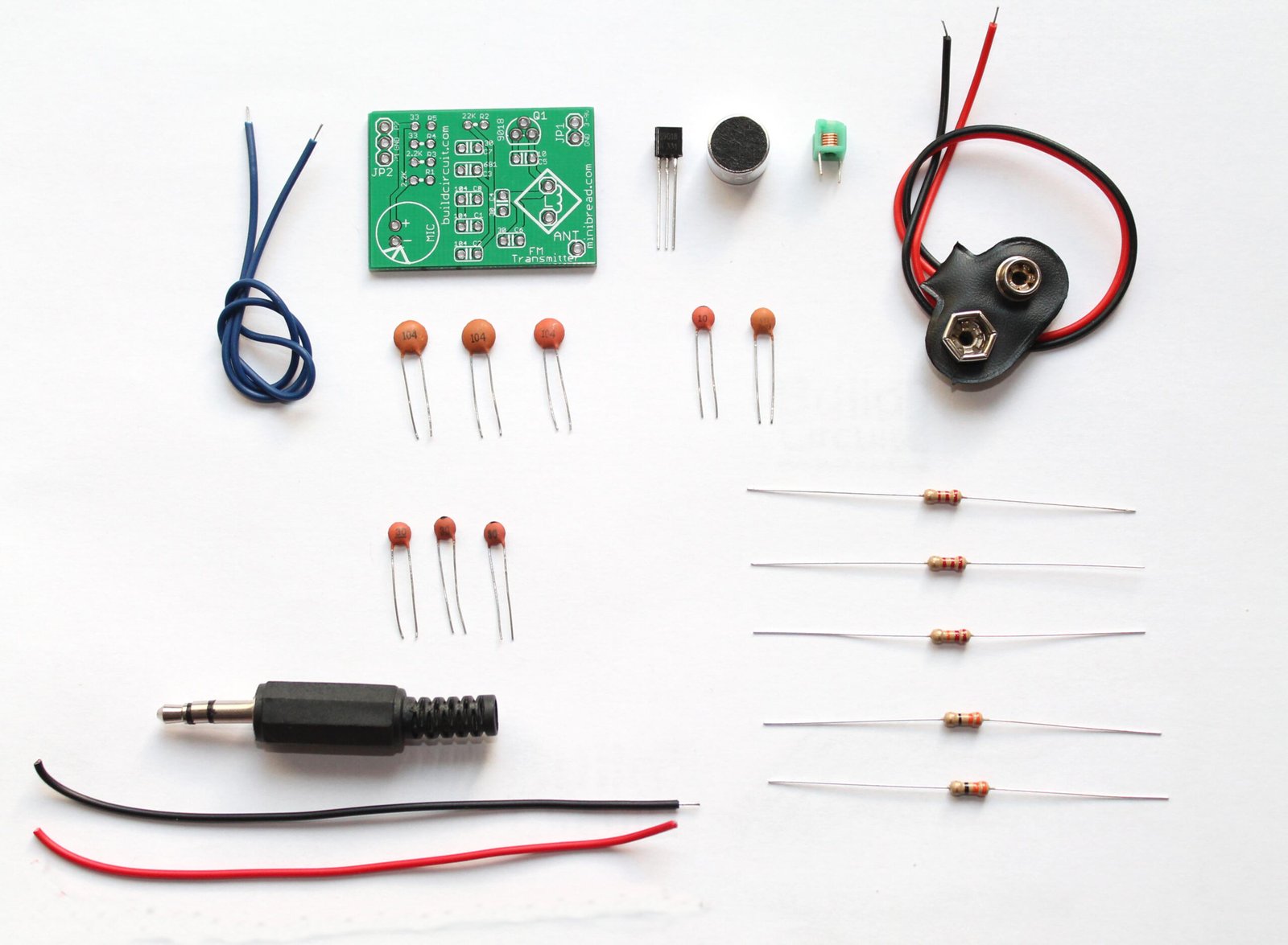
Here’s one of the easiest, simplest and the most popular FM transmitter for amateurs and electronics beginners. With this DIY kit, you can transmit your voice or audio over an ordinary FM radio within the FM broadcast band. It is a DIY kit designed by Sagar Sapkota. You can buy this kit from BuildCircuit Store. The best thing about this transmitter is that you don’t have to make your own inductor for this kit. Making an inductor is bit hard for amateurs. Besides, this kit is not only capable of transmitting voice using microphone but also transmitting music from your music player. (more…)

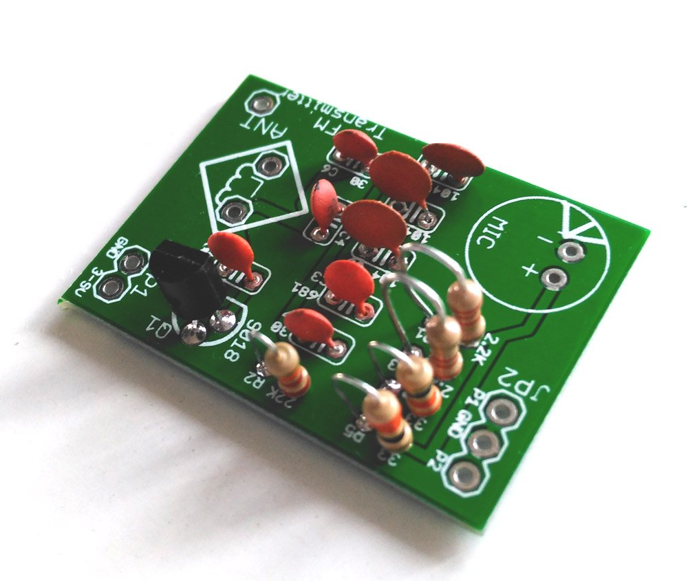
Assembly tutorial- FM transmitter DIY kit

If you have to come to this page directly from a search site, please go to this article first. This is the second article that givesĀ  assembly instructions for FM transmitter kit. Please click here for the first article.

In this article, we will see how to assemble the FM transmitter DIY kit.

First of all, look at the schematic and PCB image given below.

FM TRANSMITTER DIY KIT (3) (more…)

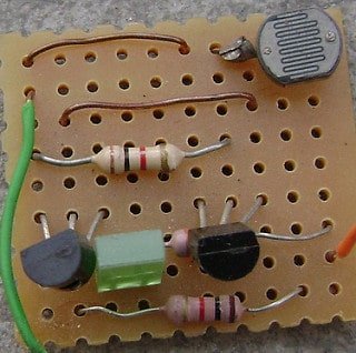
Dark sensor using two transistors

This works same as the other dark detector circuit. When light is falling on LDR, its low resistance drives transistor Q1-BC547 into conduction. This keeps transistor Q2 cut-off due to low base bias. The D1-LED does not get power as long as ambient light falls on LDR. When the resistance of LDR becomes high in darkness, transistor Q1 stops conducting and transistor Q2 starts conducting to turn on the D1-LED.

Datasheet of BC547:Ā http://www.datasheetcatalog.org/datasheet/fairchild/BC547.pdf

Click the video below to see the output.


Ā Components for this experiment are available at buildcircuit.net.

components 2

Buy now button


Basic RC circuit

For the circuit to work as light operated musical bell, we need to connect the SW1- switch to N/C terminal of relay. LDR has to be kept in a dark case.

AM receiver from dark sensor

In this case, LDR has been replaced with capacitor C1-0.01uF and resistor R3-1K has been replaced with L1 & VC1. In place of a LED, a Piezo Diaphragm has been kept.

We just need to add inductor, capacitor and a piezo diaphragm to convert a dark detector to an AM radio.

Building a circuit on a breadboard

A breadboard is a device for testing temporary electronics projects. Components used to test a circuit can be reused for other projects. None of the components are damaged.

Almost all people start to learn electronics using breadboard because it is the simplest way of making circuit. The photograph shows a typical small breadboard which is suitable for beginners building simple circuits with one or two ICs (chips).

Search for products

Back to Top
Product has been added to your cart