Assembly Tutorial of Amarino Nano 1.0

Amarino Nano 1.0

Please visit this page first to know about Amarino Nano.

Assembly process of this kit is very easy. If you have basic soldering knowledge, you can assemble the board within half an hour.

You can directly visit BuildCircuit’s Flickr page and see all the assembly steps.

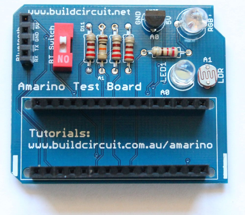
If you look at the PCB, you will see that the silkscreen labels are enough to guide you to solder the components properly.

PCB

Before you start, make sure that you have all the required components.

Here’s the list of components:

  • 1 x Arduino Nano
  • 1 x Bluetooth adapter
  • 1 x Amarino Nano PCB
  • 2 x 15 pin female headers
  • 1 x 4 pin female header
  • 1 x Red Color 1P DIP switch
  • 1 x LM35DZ temperature sensor
  • 1 x 5mm LED
  • 1 x RGB LED- common cathode
  • 1 x photo resistor
  • 4 x 220 Ohm resistor
  • 1 x 10K Ohm resistor

Now, follow these steps:

1. Always start with the small components. So, solder all the resistors first. Solder 220 Ohm resistors.

Step 2- Solder resistor that connects to D11

2. Solder 10K Ohm resistor and the photo resistor

Step 3- Solder 10K Ohm resistor

3. Solder LM35DZ temperature sensor.

Step 5- Solder LM35

4. Solder 1P DIP switch, the one in RED color. This switch has to be turned off while uploading the Arduino sketch.

Step 6- Solder 1P DIP switch

5. Solder 5mm white LED

Step 7- Solder 5mm LED

6. Solder common cathode RGB LED

Step 8- Solder RGB LED Step 8.2- RGB LED top view

7. Solder 4 pin female header for Bluetooth moduleStep 9- Solder 4pin female header

8. Solder 2pcs 15 pin female header to stack the Arduino NanoStep 10- Solder 15 pin female headers

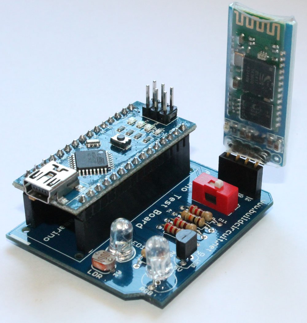
9. Stack the Bluetooth module and the Arduino Nano on the correct female headers. Your Amarino Nano board is ready to use. Visit this page for experiments.

Step 11- Fix Arduino Nano and Bluetooth Module

10. Connect a mini USB cable to operate the kit.

Connect USB cable and use the kit

See the following links:

1. About Amarino Nano 1.0

2. Experiments with Amarino Nano 1.0– You will get all the Apps and Arduino sketches on this page.

3. All the images on Flickr


Where can you buy this kit ?

The kit is available at BuildCircuit Store (www.buildcircuit.com.au- Free Shipping in Australia)

Amarino Nano-1-1Buy now button

Amarino Nano 1.0

Amarino Nano 1.0

amarino nano

[mpc_vc_quote quote=”Amarino Nano 1.0 kit facilitates communication between Arduino Nano and Android applications via Bluetooth. “]

Amarino Nano Output

Amarino Nano is a very simple kit for experimenting with Amarino toolkit– a quick prototyping application based on Android. However, you don’t essentially need Amarino toolkit to experiment with this kit.

It works with many other apps made for Android-Arduino communication via Bluetooth. You can also use this as a simple shield for Arduino Nano.

Amarino Nano is based on: 

  1. Arduino Nano– You need an Arduino Nano for Amarino experiments.
  2. Amarino toolkit application: Amarino toolkit is an Android application. Read more…

amarino app

3. Bluetooth communication medium: You will need a Bluetooth adapter module to make communication between Arduino Nano and Amarino toolkit.

What can Amarino Nano do: 

Like any other Amarino kits (Amarino DIY shield, Amarino evaluation shield), Amarino Nano 1.0 basically facilitates interaction between Arduino and Android via Bluetooth communication medium.

Features: 

  1. Control RGB LED: You can control an RGB LED from your Amarino application. In this experiment, you transmit control signals from Android to Arduino. Watch this video. See all the steps.
  2. Display LDR sensor data on Sensor Graph: You can see light sensor data and a simple graph on your Android phone interface. The sensor data is transmitted from Amarino Nano 1.0 kit to the phone. In this experiment, you transmit sensor signals to your Arduino and vice versa. Watch this video
  3. Display temperature sensor data on phone: You can see temperature sensor data (from LM35) on your Amarino application interface. In this experiment too, you transmit temperature sensor signals to your Arduino and vice versa. Watch this video.
  4. Control 5mm LED : You can control a 5mm white LED present on the kit. You can simultaneously control the LED and see sensor data. In this experiment, you transmit and receive signals from Android to Arduino and vice versa simultaneously. You can see in the experiment no.3.
  5. Use as Arduino Nano Shield: You can use this kit to experiment with Arduino Nano. You don’t need any Android app for that 🙂 .
  6. Test any Android app for Arduino: You can test any Android App made for Android-Arduino communication via Bluetooth. You can find several apps on Google Play.
[mpc_vc_deco_header type=”h6″ align=”left” text=”What does the kit package include”]

Amarino Nano 1.0 Assembled: 

Amarino Nano 1.0 “assembled version” has all the components assembled on the PCB board. In addition to the circuit board, you will get the following:

1. Bluetooth adapter module

2. Arduino Nano 1.0 (Chinese version with CH340G chipwith mini USB cable

Amarino Nano 1.0

Amarino Nano 1.0 DIY kit:

Amarino Nano 1.0 comes with all the components required to build the kit. With basic soldering knowledge you can easily build the kit.

You will get the following components:

  1. 1 x PCB- Click on the link to see how the PCB looks. You will get all the direction for soldering by seeing on the PCB. It’s very easy.
  2. 4 x 220 Ohm resistors: These resistors are current limiters for RGB and 5mm white LEDs.
  3. 1 x 10K Ohm resistor: This resistor is connected to LDR (photo resistor, light sensor) forming a voltage divider network.
  4. 1 x Light dependent resistor(LDR)/ Photoresistor: This sensor is used for sensor graph experiment.
  5. 1 x LM35 temperature sensor: This temperature sensor is used for transmitting temperature data to the Amarino application.
  6. 1 x 1P DIP switch: This switch is used for switching on/off the Bluetooth module while programming the Arduino Nano. It is not a power on/off switch.
  7. 1 x 5mm LED
  8. 1 x RGB LED: This is used for RGB lamp experiment. You can control the LED with RGB Amarino application.
  9. 1 x 4 pin female header: This header is used for stacking the Bluetooth adapter module.
  10. 2 x 15 pin female headers: These headers are used for stacking the Amarino Nano.
  11. 1 x Arduino Nano with USB cable: You will get a Chinese version of Arduino Nano with a mini USB cable. It has CH340G chip.
  12. 1 x Bluetooth adapter module: This Bluetooth module facilitates communication between Arduino Nano and Amarino kit.

amarino nano

How to assemble the DIY version of Amarino Nano 1.0: 

  1. You can get the assembly tutorial on this page.
  2. You can see all the image on Flickr and get soldering idea.

Applications and Libraries

Before you begin your experiments with Amarino Nano 1.0, you need to download the following:

amarino app

  • Download Amarino Library for Arduino and move it to the Libraries folder. You can check here if the Amarino team has upgraded the library. It’s always good to use the updated version :) .  If the link does not work, you can download the library from this link. 
  • Other applications:

a. RGB LED Control application This application is for controlling the RGB LED.

multicolor lamp

If you need the source code, download it from here. The source code is optional and useful only for Android programmers. If the link does not work, download it from here.

b. Sensor graph application: This application is for getting LDR sensor signals from Arduino board. Source code for this application can be downloaded from here.

sensor graph

c. LM35 temperature sensor application:  With this application, you can transmit LM35 temperature sensor data to your Amarino application.

temperature sensor

Source code for this application can be downloaded from here.

Experiments:

As you can see from the schematic, the pins of Arduino Nano which are connected to the sensors and other components:

Analog Pins: 

A1: Connected to Photoresistor

A0: Connected to LM35DZ temperature sensor

Digital pins:

RGB LED: D3: Red, D5: Blue, D7: Green.

D11: 5mm White LEDAmarino Nano1

1. RGB LED Control experiment: In this experiment, you control the RGB LED with the RGB multicolor lamp application.

2. Sensor Graph: In this experiment, you can fetch the light sensor data on your Amarino interface. The Arduino sends sensor data to your phone.

3. Temperature sensor data on your phone: In this experiment, you can fetch the Lm35 temperature sensor data on your Amarino application interface. The Arduino sends sensor data to your phone and your phone can control the 5mm LED present on the Amarino Nano kit.

Where can you buy this kit ?

The kit is available at BuildCircuit Store (www.buildcircuit.com.au- Free Shipping in Australia)

Amarino Nano-1-1Buy now button

Experiments with Amarino Nano 1.0

If you have come to this page from a search engine, please read this page first, you will eventually come back to this page again. The first page gives you the idea of Amarino Nano 1.0 and its features.

Steps for experiments: 

Before you start the experiment, stack the Arduino Nano and Bluetooth modules on the headers of Amarino Nano. This is how you do that:

Amarino Nano-1-1

Then connect it to your computer for programming using the provided USB cable. Please remember that you need to turn off the RED colored 1P-DIP switch while uploading your sketch to your Arduino.

For all the experiments, you have the following things in common:

Step 1: Amarino Toolkit MAIN application: This is the main Amarino application to be installed on your Android phone. There are other applications which work only after installing the main application. If the link does not work, download the application from here.

Step 2: Amarino Library for Arduino: Download it and move it to the Libraries folder. You can check here if the Amarino team has upgraded the library. It’s always good to use the updated version :) .

If the given link does not work, you can download the library from this link. 

After installing the Amarino main application and Amarino library, we move to the following steps:

Step 3: Pair up the Bluetooth adapter module with the Bluetooth of your Android phone. The pairing code is 1234. 

After installing the Bluetooth adapter on the Amarino Nano kit, switch on the Bluetooth function of your phone, open the Amarino application and connect each other using the pairing code 1234. You can see the MAC ID of the Bluetooth adapter on the Amarino application interface. On the image shown below, you can see that there are two Bluetooth adapters with two different names and IDs registered on the application. Pressing the “Connect” button connects the application to the chosen adapter. You can connect only one adapter at one time.

Once the adapter is paired up, you don’t need to pair it again. 

Amarino Interface

A low cost general Bluetooth adapter is enough for this shield. You can purchase one at www.buildcircuit.com.au.

Look at the schematic before you start:

On the schematic given below you can see how the components are connected to Arduino Nano. Seeing the schematic you can expect the output of your projects.

Amarino Nano1

Experiment 1- RGB LED Control: watch this video.

Amarino Nano-1-1

This is how you stack Arduino Nano and Bluetooth modules on the headers.

Remember to turn off the RED color 1P DIP switch while uploading your Arduino sketch.

RGB LED is connected to digital pins 3(RED), 5(GREEN) and 6(BLUE).

RGB control application multicolor lamp

  • Open the application and control your RGB LED. As you move the slider, the color on the RGB LED changes. Remember to switch on the 1P DIP switch, otherwise, it won’t work. 

The multicolor lamp application

Experiment 2: Sensor Graph display

Switch off the RED color 1P DIP switch while uploading your Arduino sketch.

The photoresistor/LDR is connected to A1 and the 5mm white LED is connected to D11.

  • Download the sensor graph application and install it on your phone.
  • Download the Arduino source code and upload it to your Arduino Nano. NOTE: You need to switch off the 1P DIP switch while uploading the sketch. After uploading switch it on again.
  • Set Bluetooth MAC ID. It is different for all Bluetooth modules. My Bluetooth module has MAC ID: 98:D3:31:70:3A:98, so, I used that. You will have a different MAC ID for your module.

Sensor Graphsensor graph

  • Open the application and see the sensor data on your phone. You may also control the 5mm LED simultaneously. Remember to switch on the 1P DIP switch, otherwise, it won’t work. 

sensor graph (2)

Experiment 3: LM35 temperature sensor data display

Switch off the RED color 1P DIP switch while uploading your Arduino sketch.

LM35 temperature sensor is connected to A0.

temperature sensor log intemperature sensor

  • Open the application and see the sensor data on your phone. You may also control the 5mm LED simultaneously. Remember to switch on the 1P DIP switch, otherwise, it won’t work. 

temperature sensor datatemperature sensor


Where can you buy this kit ?

The kit is available at BuildCircuit Store (www.buildcircuit.com.au- Free Shipping in Australia)

Amarino Nano-1-1Buy now button

Search for products

Back to Top
Product has been added to your cart