3.5A UNIPOLAR STEPPER MOTOR DRIVER
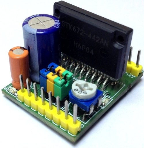
Unipolar stepper motor driver can drive unipolar motor up to 3.5A and supply range 10 To 50V DC. The board has been designed using STK672-442AEN IC. The STK672-442AN is a hybrid IC for use as a unipolar, 2-phase stepper motor driver with PWM current control and Micro-stepping.
FEATURES
- Supply Up to 50V DC Input
- Logic Supply 5V DC Input
- Load Current 3.5Amps
- Stepper Motor: 5 Wires, 6 Wires, 8 Wires (Unipolar)
- Built-in over current detection function, over heat detection function (Output Off)
- Fault 1 signal ( Active Low) is output when overcurrent or over heat is detected
- Fault 2 signal is used to output the result of activation of protection circuit detection at 2 levels.
- Built-in power on reset function
- A Micro-step sin wave driven driver can be activated merely by inputting an external clock.
- The Switch timing of the 4-phase distributor can be switched by setting an external pin (Mode3) to detect either the rise or fall, or rise only, of clock input.
- The Enable pin can be used to cut output current while maintaining the excitation mode.
- With a wide current setting range, power consumption can be reduced during standby.
- No Motor noise during hold mode due to external excitation current control.
- Incorporating a current detection resistor (0.122Ω: resistor tolerance 2%), motor current can be set using two external resistors.
- Phase is maintained even when the excitation mode is switched. Rotational direction switching function
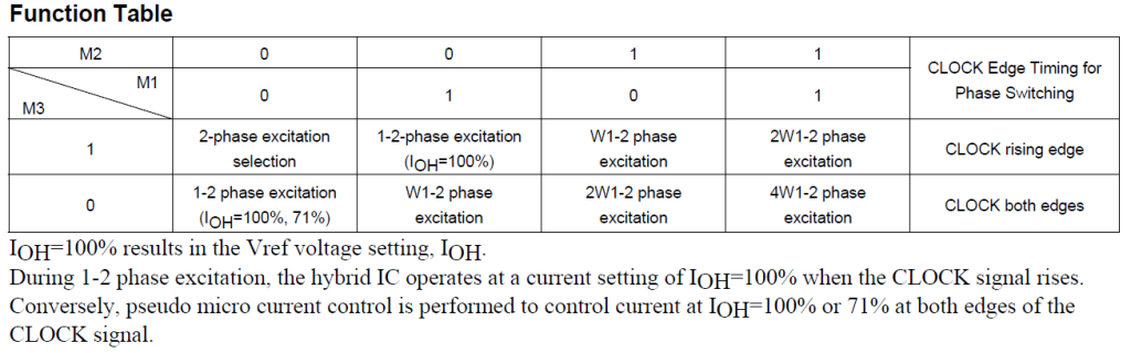
- External pins can be used to select 2, 1-2 (including pseudo-micro), W1-2, 2 W1-2, or 4W1-2 excitation.
- Clock Input : Input frequency 20Khz when using both edge, Or 50Khz when using one edge
- Minimum pulse width 20us When using both edge Or 10us when using one edge
- M3: Jumper J3-Open the excitation phase moves one step at a time at the rising edge of the CLOCK pulse.
- M3: Jumper J3-Closed the excitation phase moves alternately one step at a time at the rising and falling edges of the CLOCK pulse.
- Do not Change direction during the 7us interval before and after the rising and falling edges of CLOCK input.
- Enable : Normally High for Normal Operation, Pull down control of excitation drive output A, AB, B, and BB, and selecting operation/hold status inside the HIC
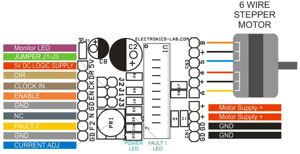
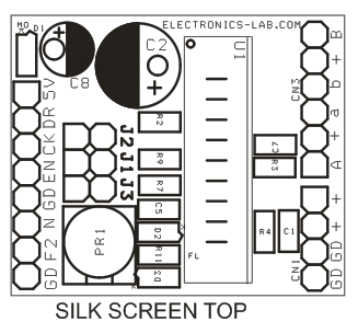
CONNECTIONS, LEDS AND JUMPERS
CN 1 : Supply Input up to 50V DC
CN2 : 1 Pin 5V DC, 2 Pin Direction, 3 Pin Clock Input, 4 Pin Enable, 5 Pin GND, 6 NC, 7 Pin FLT2, 8 Pin GND
CN3 : Stepper Motor Connection
D1 LED : Excitation Monitor ( Motor Pulse Indicator)
D3 LED : Power LED
D2 LED : Fault 1 LED On When Over Current, Over Heat
Jumper J1, J2 Micro-Stepping
Jumper J3 The Switch timing of the 4-phase distributor can be switched by setting an external pin (Mode3) to detect either the rise or fall, or rise only, of clock input.
SCHEMATIC

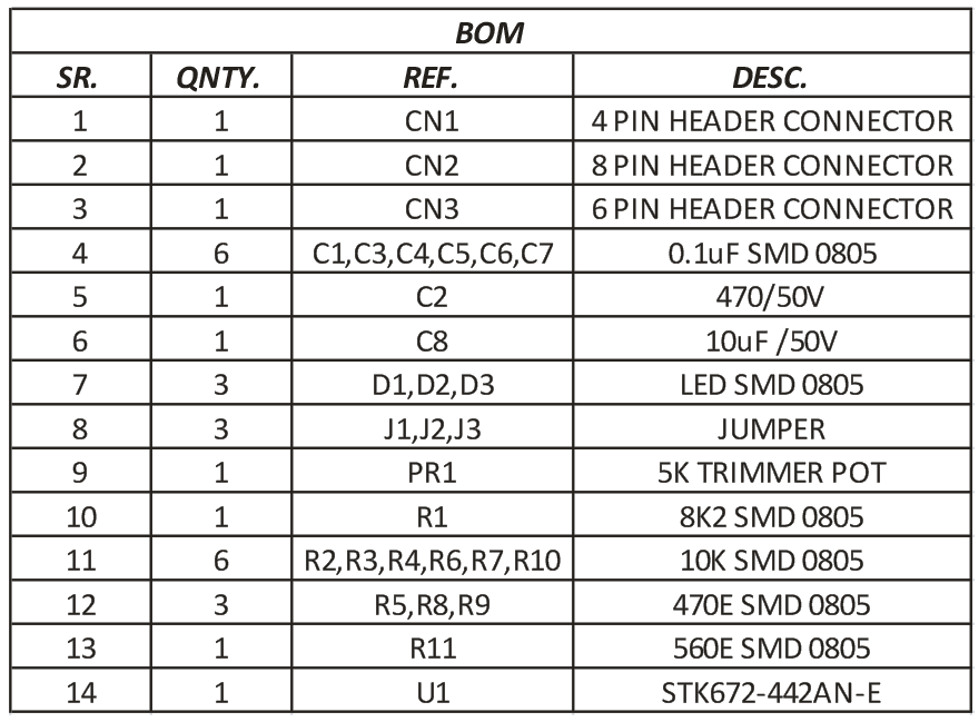
PARTS LIST
CONNECTIONS
MICRO-STEPPING
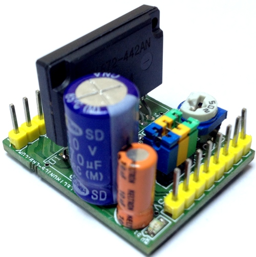
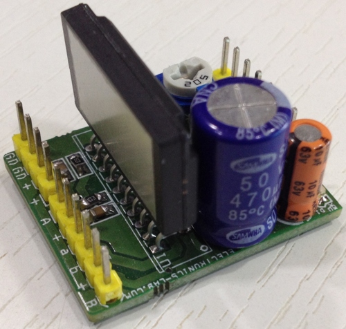
PHOTOS
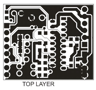
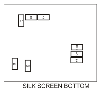
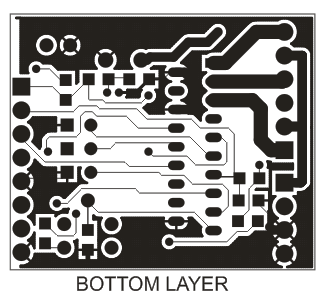
PCB
🛠️ Dive into our collection of DIY Kits, 🔊 Audio Amplifiers, Digital Scoreboards, FM transmitters, and more!
🎶 Explore endless possibilities at our new store.