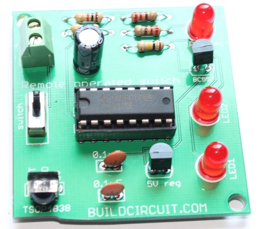
Assembly- Breadboard power supply DIY kit
![]()
This is the assembly tutorial of ‘breadboard power supply DIY kit’. You can get all the details of this kit at this link.
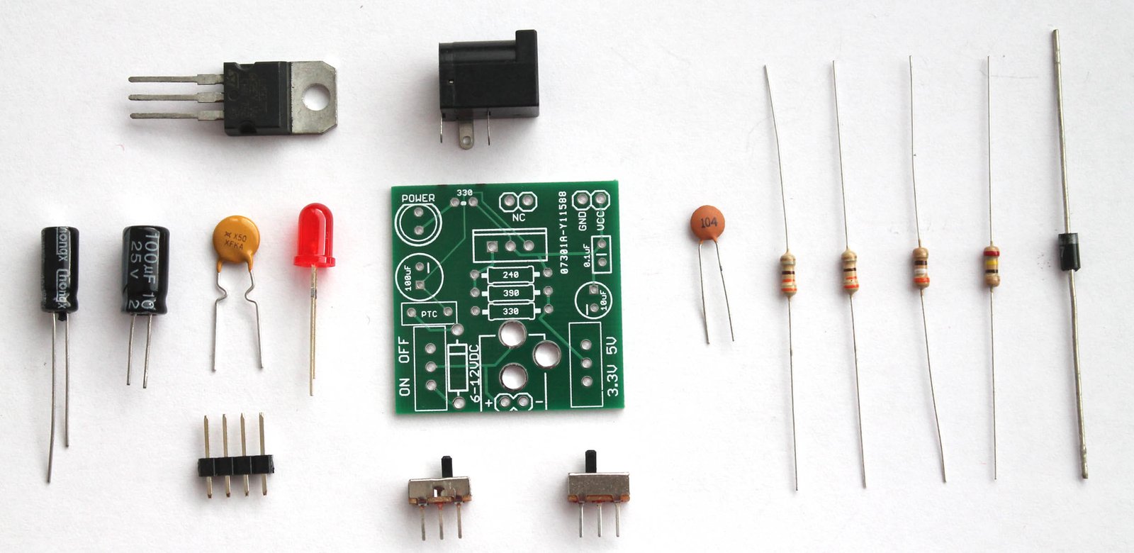
You will get the following components with the kit package. You can purchase this kit at buildcircuit.com.au. The web store is operated by BuildCircuit team.

![]()
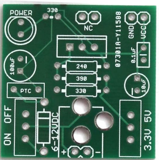
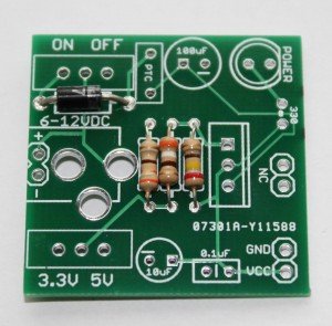
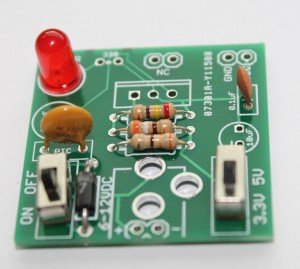
Look at the PCB below.You can see the silkscreen indicators/labels of the components. If you follow the labels correctly, you can easily assemble all the components on to the circuit board.
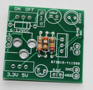
Step 1: Start with resistors. Solder the three resistors- 330R, 390R and 240R. Click on the resistors to get the color code.
Step 2: Then, fix the diode 1N4001. You can also use 1N4004 or 1N4007. All work the same way.
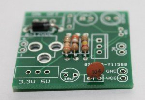
Step 3: Fix 0.1uF (code-104) capacitor.
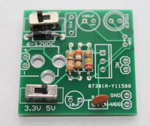
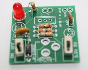
Step 4: Fix the 2pcs of SPDT switch. One switch is for ON/OFF function and the other is for switching 3.3V and 5V.
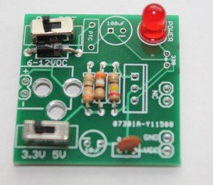
Step 5: Fix the 5mm red LED. It works as a power indicator.
Step 6: Fix the PTC resettable fuse (500mA). This is a handy little device that can save your system from burning. A resettable fuse (also known as a PTC) is a resistor that has very unique properties.
For this kit, if your circuit tries to draw more than 500mA of current (if you have a bad short for instance) the PTC would ‘trip’ (by heating up). The increased resistance (trip state) would break the circuit and allow only a small leakage current.
Step 7: Solder the 330R resistor. It works as current limiting resistor for the 5mm LED.
Step 8: Solder 100uF and 10uF capacitors. Please be careful with the polarity. Wrong polarity will burn the components. The silkscreen indicators should help.
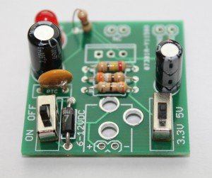
Step 9: Solder the LM317 chip and DC barrel.

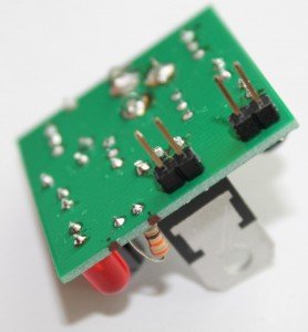
Step 10: There are 2pcs of 2-pin male header for fixing the circuit board into the breadboard holes. You need to solder them as shown on the image below.
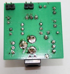
Give a close look.
Step 12: Fix the power supply into your breadboard using the male headers. Power up the circuit with any DC supply (6-37V), it will give two outputs- 3.3V and 5V(one at a time).

The kit is ready to use for your projects. Fix your project components on the remaining part of the breadboard.

Recommended links:
- How to make power supply using LM317 ?
- Assembly Tutorial
- Buy the kit at buildcircuit.net
- Video- How to make a LM317 power supply
- Images on Flickr
- Schematic-breadboard-power-supply
You can buy this wonderful DIY kit at buildcircuit.net. BuildCircuit.ORG is the online store owned and operated by BuildCircuit team.
![]()
🛠️ Dive into our collection of DIY Kits, 🔊 Audio Amplifiers, Digital Scoreboards, FM transmitters, and more!
🎶 Explore endless possibilities at our new store.