Assembly- Breadboard power supply DIY kit

button_prev_page

This is the assembly tutorial of ‘breadboard power supply DIY kit’. You can get all the details of this kit at this link.

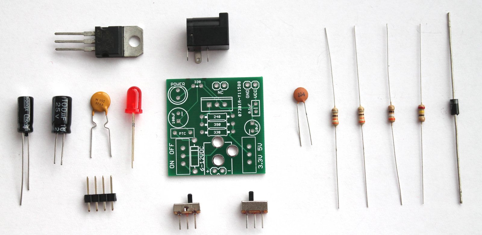
You will get the following components with the kit package. You can purchase this kit at buildcircuit.com.au. The web store is operated by BuildCircuit team.

Breadboard power supply- components

try this also

Look at the PCB below.You can see the silkscreen indicators/labels of the components. If you follow the labels correctly, you can easily assemble all the components on to the circuit board.

PCB

PCB dimension: 31.75mm x 31.75mm

Step 1: Start with resistors. Solder the three resistors- 330R, 390R and 240R. Click on the resistors to get the color code.

Step 1- solder resistors 330R, 240R and 390R

Step 2: Then, fix the diode 1N4001. You can also use 1N4004 or 1N4007. All work the same way.

Step 2 Solder 1N4007 diode

Step 3: Fix 0.1uF (code-104) capacitor.

Step 3 Solder 0.1uF capacitor

Step 4: Fix the 2pcs of SPDT switch. One switch is for ON/OFF function and the other is for switching 3.3V and 5V.

Step 5 Solder another SPDT switch

Step 5: Fix the 5mm red LED. It works as a power indicator.

Step 6 Solder 5mm LED

Step 6: Fix the PTC resettable fuse (500mA). This is a handy little device that can save your system from burning. A resettable fuse (also known as a PTC) is a resistor that has very unique properties.

For this kit, if your circuit tries to draw more than 500mA of current (if you have a bad short for instance) the PTC would ‘trip’ (by heating up). The increased resistance (trip state) would break the circuit and allow only a small leakage current.

Step 7 Solder resettable fuse 500mA

Step 7: Solder the 330R resistor. It works as current limiting resistor for the 5mm LED.

Step 8 Solder the last 330R resistor

Step 8: Solder 100uF and 10uF capacitors. Please be careful with the polarity. Wrong polarity will burn the components. The silkscreen indicators should help.

Step 9 Solder 100uF and 10uF capacitors

Step 9: Solder the LM317 chip and DC barrel.

Step 10 Solder LM7805 and DC barrel

Step 10: There are 2pcs of 2-pin male header for fixing the circuit board into the breadboard holes. You need to solder them as shown on the image below.

Step 11 Solder the male headers for breadboard

Give a close look.

Step 11-Close up

Step 12: Fix the power supply into your breadboard using the male headers. Power up the circuit with any DC supply (6-37V), it will give two outputs- 3.3V and 5V(one at a time).

Step 14- 3 Powering up the breadboard power supply - Copy

The kit is ready to use for your projects. Fix your project components on the remaining part of the breadboard.

Step 13 Powering up the breadboard power supply

Recommended links:

  1. How to make power supply using LM317 ?
  2. Assembly Tutorial
  3. Buy the kit at buildcircuit.net
  4. Video- How to make a LM317 power supply
  5. Images on Flickr
  6. Schematic-breadboard-power-supply

You can buy this wonderful DIY kit at buildcircuit.net. BuildCircuit.ORG is the online store owned and operated by BuildCircuit team.

try this also

Gallery- Breadboard power supply DIY kit

This post contains all the assembly images of ‘breadboard power supply using LM317- DIY kit’. You can click on the images and see the steps. We have not put the images serially, but once you click on the image, it shows the step numbers.

Download all the images at once

The images of this post are related to the following articles:

Breadboard power supply- components try this also

breadboard power supply Step 2 Solder 1N4007 diode Step 4 Solder SPDT switch Step 5 Solder another SPDT switch Step 6 Solder 5mm LED Step 7 Solder resettable fuse 500mA Step 8 Solder the last 330R resistor Step 9 Solder 100uF and 10uF capacitors Step 9 Solder 100uF and 10uF capacitors-2 Step 10 Solder LM7805 and DC barrel Step 10 solder LM7805 and dC barrel-2 Step 11 Solder the male headers for breadboard Step 11-Close up Step 12 Fixing the breadboard power supply on breadboard Step 13 Powering up the breadboard power supply Step 14- 2 Powering up the breadboard power supply Step 14- 3 Powering up the breadboard power supply - Copy Step 1- solder resistors 330R, 240R and 390R Step 3 Solder 0.1uF capacitor

You can buy this DIY kit at BuildCircuit.org. The store is operated by BuildCircuit team.

try this also

Gallery- one transistor FM transmitter

GO TO THE ARTICLE PAGE

step11- another angle StripBoard with columns The back side of the strip board connection of wires to stereo jack step3- fix 10pF (C5)capacitor Step 15- Solder the antenna Step 14- Fix 9V connector step 13- Solder the stereo speaker jack Step 13- Another angle Step 13- a close view Step 12- Solder inductor (2) Step 12- solder inductor Step 13- a close view (2) Step 11- Fix the electret microphone step 11- microphone step 11- solder 30PF(C6) step 11- another angle1 Step 10- Fix R¤ and R3- 33Ohm resistors step 10- another angle step 8- top view step 9- another angle step 9- Solder C8(0.1uF) Step 7- Solder 0.1uF(C2) step 8- another angle Step 8- Solder R1(2.2K) Step 6- Fix 680pF(C3) and a jumper wire connecting to GND Step 5- Fix 30PF(C4 ) and a jumper wire connecting to GND step 4- Fix 30pF(C7) step 1- solder S9018(Q1) transistor step 2- fix 22k(R2) and 2.2K(R3)

You can similar kit (FM transmitter) to cart

BC-0012

1 Transistor FM Transmitter DIY Learning Kit

$12.89
Item Location: Sydney, Australia You can use this FM

Other DIY Kits from BuildCircuit.COM

G5CD017E761B94

2CH X 100W + 200W 2.1 Channels Bluetooth Audio Amplifier Board - TSA7500

$81.32
TSA7500 2CHx100W + 220W 2.1 channels audio amplifier
BC-8342

LED Chaser Using NE555, CD4017, Infrared Receiver And Photoresistor

$13.50
The kit does work normally like a normal

CD4026- 1 Digit Up Counter Module

$6.71
  • It works as an UP counter. You can
BC-3014A

3 Digit Digital Objects Counter With Laser Module

$20.28$27.06
This is 3 digits digital object counter kit
BC002

LCD Shield For Arduino-Bluetooth Android Hobbyists

$16.21
This LCD shield is designed for experimenters who
COU-18

1.8" Photoresistor And Laser Operated Medium Digital Objects Counter

$33.84
This is an upgraded version of the previous
Sold out
COU-23

Photoresistor And Laser Operated Large Digital Objects Counter With 2.3" Displays

$40.63
A laser light module illuminates the photoresistor continuously
COU-902

2.3" common cathode seven segment display driver

$20.28$27.06
This is a CD4026 based up counter driver

Search for products

Back to Top
Product has been added to your cart