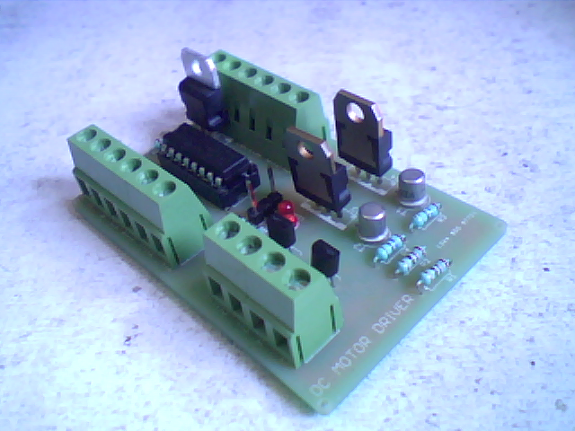
DC MOTOR DRIVER USING L293D
This project is a DC motor driver, suitable for motors of low or medium power. Allows controlling up to 6 motors or 3 motors if you want to control the rotation of the motors.
DESCRIPTION
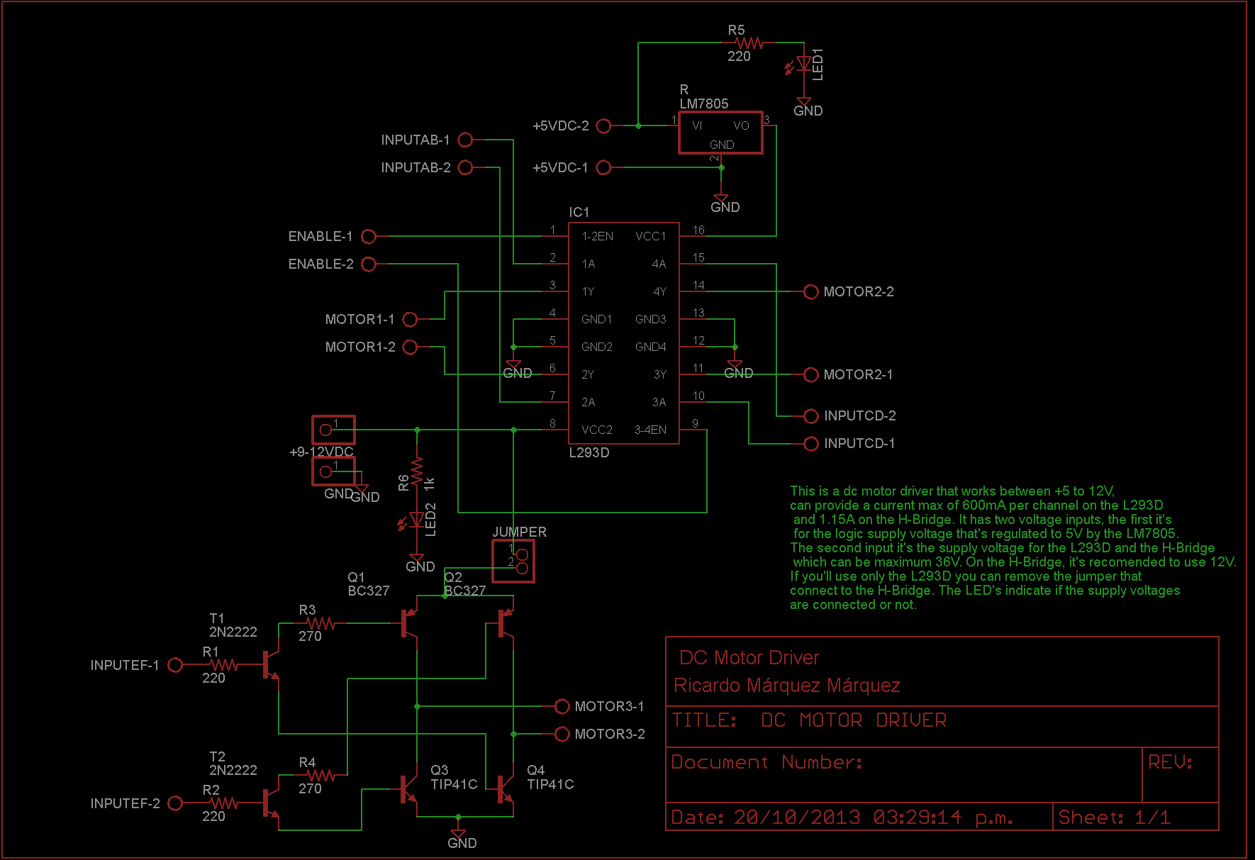
The controller is build around the IC L293D that can provide 600mA per channel, and a H-Bridge designed with transistors NPN and PNP transistors, than can provide 1.15A per channel.
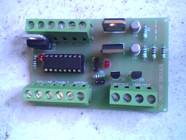
The controller has the following connections:
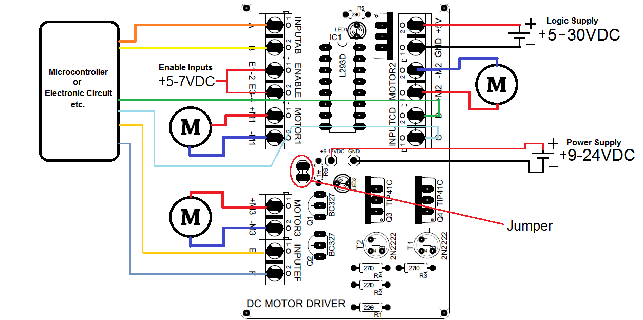
- INPUTS (A, B, C, D ,E, F). These are receiving the analog or digital signals that can be sent for example, from a microcontroller.
- ENABLE (E1-2, E3-4). These activate the inputs from the L293D. The supply voltage can’t be higher than 7V.
- OUTPUTS (+M1, -M1, +M2, -M2, +M3, -M3). Here is where the motors should be connected.
- +9-12V. Here’s where is connected a supply voltage that will give power to the motors. This input, gives voltage in the L293D and the H-Bridge, the supplied voltage have to be 36V max, but for the H-Bridge it’s recommendable to use 24V max. (In case you want to use only the L293D, you can remove the jumper).
- +5V. This input receive the logic supply voltage for the L293D. You can connect a supply voltage higher than 5V because this input it’s connected to a voltage regulator (LM7805), but you not must to exceed 30V.
SCHEMATIC
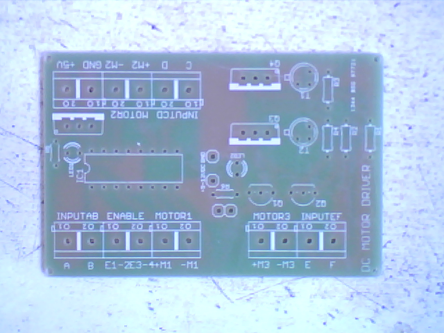
CONNECTIONS
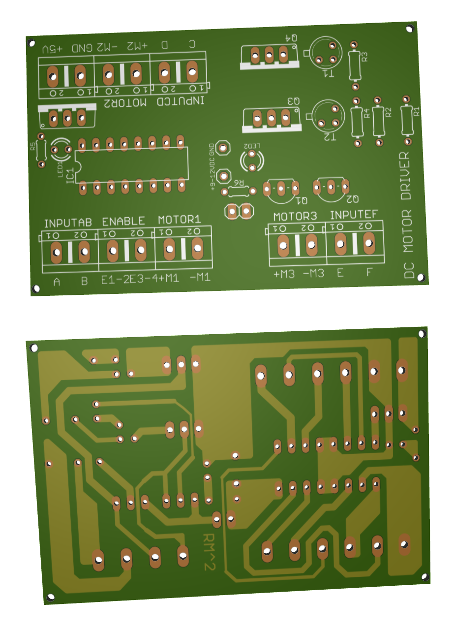
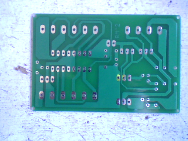
PCB
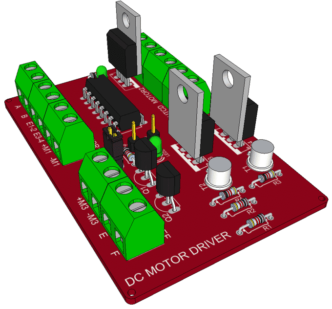
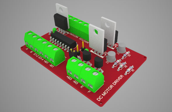
3D PCB
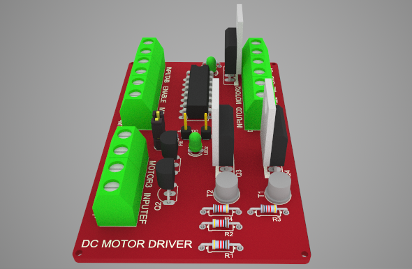
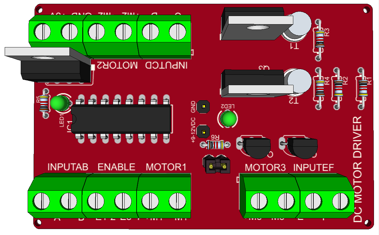
 3D PCB Render
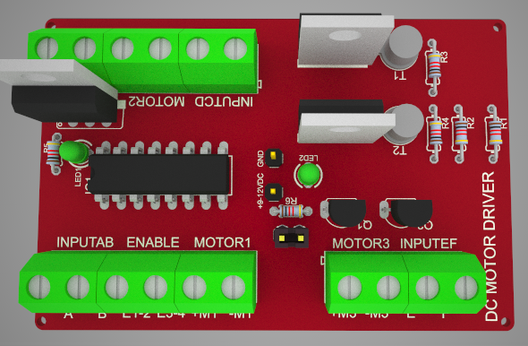
🛠️ Dive into our collection of DIY Kits, 🔊 Audio Amplifiers, Digital Scoreboards, FM transmitters, and more!
🎶 Explore endless possibilities at our new store.