


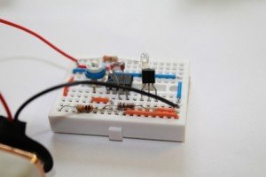
Experiments with LM358
Description: LM358 is also one of the types of operational amplifier. LM358 consists of two independent, high-gain, frequency-compensated operational amplifiers designed to operate from a single supply over a wide range of voltages.
This module can also be used for testing an LDR, a phototransistor and a photodiode. You just need to replace an LDR with phototransistor or photodiode, the circuit simply works. You can try this project using 741 IC also.
You can get more LM358 projects from the following links:
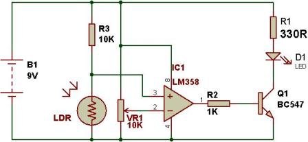
Project 1: LDR and LM358
This is a simple dark sensor circuit. When you block light falling on LDR, the LM358 switches on the LED.


Project 2: Photodiode and LM358
Remove LDR and insert a photodiode, it works instantly. Depending upon the light level of your room, you might have to adjust the variable resistor to adjust sensitivity of the circuit.


Project 3: Phototransistor and LM358
Remove LDR and insert a phototransistor, it works instantly. Depending upon the light level of your room, you might have to adjust the variable resistor to adjust sensitivity of the circuit.


WATCH THE VIDEO:
🛠️ Dive into our collection of DIY Kits, 🔊 Audio Amplifiers, Digital Scoreboards, FM transmitters, and more!
🎶 Explore endless possibilities at our new store.


Very good article, My son was like light control circuit for build simple robot, we try to build this circuit on Sunday.
Thank you.
momename.
did’nt work for me
First try with LDR, then try with photo transistor and photo diode. In case of photodiode and photo transistor, you should have strong light source, otherwise, it doesn’t work. However, it works if you change the sensitivity.
Everything works for me…thanks for sharing!
Thanks so much for helping young peaple like us build confidence in electronics.
I need to build a charging system for my radio. When the battery is full, it should stop power. Is it possible sir? Thank you.
I have three questions actually…
1)Why did you put 10 Kohm resistor at collector side of phototransistor and 1Kohm at the base of the NPN transistor?
2) Is it okay if I give signal to any input side of the op-amp? In this case you put phototransistor signal at pin3 of opamp and juz a signal with resistance to the pin2 of the op-amp. What will happen if you swap?
3)The circuit I am preparing is sort of theft detector. It has IR emiiter TIL38 and IR detector TIL81. I use your way for constructing circuit. It is working only if I put very strong light source. How can I do? Thanksi in advance for your kind help.
Hi, how modify to have an analogic voltage output to using as luxmeter with an arduino?. I would like to measure very low light.
Regards
Hello,
is the advantage of this that as a comparator (yes?) it is an 1/0 function rather than the transistor light detector designs that are very jittery and have a linear response?
I cannot tell from the video.
Cheers,
Oliver
please explain the circuit sir
thanks for your help for your information..but I want to replace a dc motor instead of led..what are the xhanges to be done in the circuit like changing the resistors
Please make a reply
Sir i have to compare resistance with using 2 ldr to drive the motor in both directions how should be the connection??