


How to make one transistor FM transmitter on a stripboard- page 1/2
In this article, I am going to show how to plan and make a single transistor FM transmitter on a stripboard (prototype board). This project has been tested in a 5 storey building and it works perfectly well.
You can transmit your voice or audio signals from your computer or music player to a distant FM radio. The radio picks up the signal within 88-108Mhz FM frequency band.
Before you start, you should be aware of the fact that making and using FM transmitter is illegal in many countries. Please ask your seniors or teachers if you can make this project in your country.
This project is the stripboard version of the FM transmitter DIY kit sold on buildcircuit.net. We sell all the components (including PCB) required to build this circuit.
![]()
Let’s start with the schematic:
The description of this schematic is available on this page.
Collect all the components. You can buy the components from buildcircuit.net, which is a store operated by our team. The list of components is given below:
- C1- 0.1uF capacitor (code- 104)- This optional. It doesn’t matter if you don’t have this. We have explained about this later on the description.
- C2- 0.1uF capacitor (Code- 104)
- C3- 680pF capacitor (code- 681)
- C4- 30pF capacitor (code- 30)
- C5- 10pF capacitor (code- 10)
- C6- 30pF capacitor (code- 30)
- C7- 30pF capacitor (code-30)
- C8- 0.1uF capacitor (code- 104)
- R1- 2.2K resistor (Red-Red-Red)
- R2- 22K resistor (Red-Red-Orange)
- R3- 2.2K resistor (Red-Red-Red)- Get 1K resistor also. 1K contributes to increment in transmission distance. You need to use either 1K(transmits up to 100m) or 2.2K (transmits up to 10m).
- R4- 33 Ohm resistor(Orange-orange-black)
- R5- 33 Ohm resistor (Orange-orange-black)
- Q1- S9018 transistor. Datasheet.
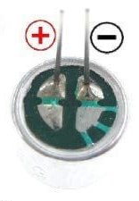
- Electret microphone.
- 5.5 Turns inductor coil.
- Stereo speaker jack
- 9V battery clip
- A 9V battery.
- 10-20cm Antenna wire.
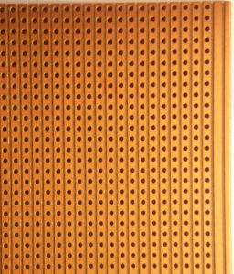
- Strip board with vertical copper columns. See the image below:
You can buy the components from buildcircuit.net. Please note that we don’t sell stripboard, but you can buy the FM transmitter PCB board along with the components. BUY NOW
Planning the project on a stripboard:
Tip 1: You should plan your project is such a way that you use minimum number of external wires and jumpers. In this project, I have used only 1 jumper to connect -ve terminal of battery. If you use too many jumpers, that may induce unwanted inductance and capacitance in the circuit and that will shift the transmission frequency of the transmitter. This applies not only to this FM transmitter project, but also to any other projects.
Tip 2: It’s absolutely OK if your soldering is bad. The only thing you should be aware of is to avoid short circuit or connection of one component to another wrong component. Besides, remember that there should not be any loose connections.
Tip 3: The inductor L1 and capacitor C4 (30pF) should be kept close.
Inductor tip: If you want to make your own inductor, you can use a 24SWG wire and make an inductor out of it. You can watch this video to know how to make an inductor.
Electret microphone: You can visit this page to know about electret microphone.
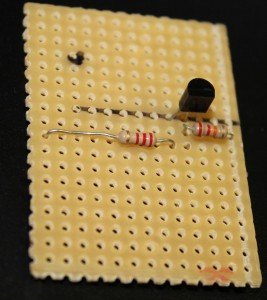
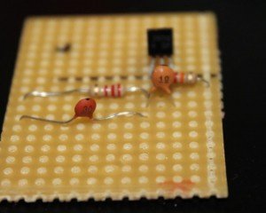
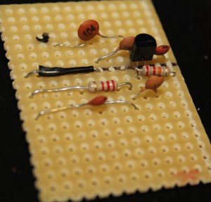
Now, look at the images below and follow the instructions:
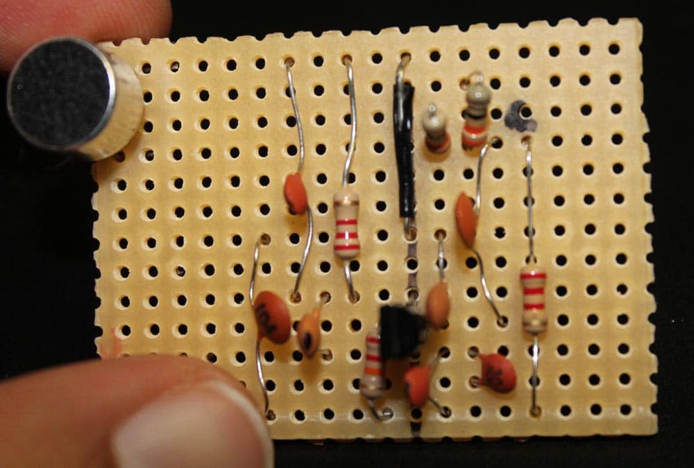
Solder S9018 transistor.
(Note that there are altogether 13 copper columns on the stripboard. Here, note that the right most column is for +9V and the leftmost column is for ground(-ve) terminal of the battery. It makes the assembly process bit easier.)

Fix 22k (R2) and 2.2K (R3). If you want to transmit up to 100meters, then use 1K in place of 2.2K.
Then, fix 30pF (C7) in parallel to R3. Also, fix a 10pF capacitor (C5) connecting to emitter and collector of the transistor.
After that, solder 30pF (C4 ) that connects to the collector and the +ve terminal of the battery. Also fix a jumper wire connecting to GND(-ve terminal of battery). Note that we have used the leftmost column for connecting -ve terminal of battery.
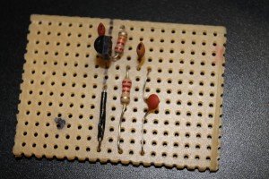
Then, solder 680pF(C3- code 681) capacitor that is connected to the base of transistor and -ve terminal of battery.

Solder C2 – 0.1uF (code- 104) connecting to the base of the transistor.
Solder R1 (2.2K). Its one end connects to C2(0.1uF) and the other end connects to the +9V line.
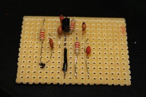
Click here to see all the images of this project.

You can buy this FM transmitter in the form of a DIY kit at BuildCircuit Store.
![]()
Related articles:
🛠️ Dive into our collection of DIY Kits, 🔊 Audio Amplifiers, Digital Scoreboards, FM transmitters, and more!
🎶 Explore endless possibilities at our new store.


will this FM Tx work with mobiles….i mean if we connect the 3.5mm jack to mobile audio pin will it work…
Yes, it works.
any alternative for S9018
what is the use of JP2 jumper point
Hello Sagar, if I remove the microphone completely, will the circuit still work?
how can i use the JP2 jumper point
how can i increase the range.