


Latch-up circuit using 555 and opto-coupler
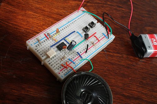
Here’s a simple latch-up circuit using 555 timer and opto-coupler MCT2E. You can also use PC817 in place of MCT2E. The NE555 timer is configured in astable mode.The components are selected in such a way that the frequency output of the astable circuit lies within the audio range. Opto-coupler, MCT2E is is used for latching the alarm.Under normal conditions, pin 4 of NE555 timer is set to ground via resistor R2(470Ohm) and its output at Pin 3 is held LOW. When switch S1 is pressed momentarily, transistor T1 (BC548) conducts to bring reset pin 4 to logic “HIGH” state, as a result, 555 timer activates and starts the sound and the LED inside the optocoupler glows and the phototransistor conducts. The transistor gets base bias via phototransistor and resistor R6(470R). The sound remains ON till you press the reset switch(S2). When switch S2 is pressed, the base of the transistor connects to the ground(0V) and resets the 555 timer bringing Pin 4 to LOW state. This disables the alarm.

What’s inside MCT2E?

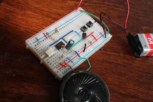
I made this project with another opto-coupler, PC817 and it works well. SEE ALL PHOTOS ON PICASAWEB.
 |
| From Latch up circuit using 555 and optocouplerJuly 16, 2012 |
Video:
Recommended Links:
🛠️ Dive into our collection of DIY Kits, 🔊 Audio Amplifiers, Digital Scoreboards, FM transmitters, and more!
🎶 Explore endless possibilities at our new store.


Hi ,
First of all , thank you for your circuit above.
I was wondering if you could help me with the following.
What would the above circuit look like if I need to drive 2 car bulbs ;one with a relay and the other with a MOSFET as Warning Flasher or car lights flasher.
I mean if we press S1 the circuit will drive the bulbs to flash at say a frequency of 1Hz, and with as close to 50% duty cycle as possible and also generates the the sound as you have already done.
I hope you could help me with that.
Many thanks.
can i get Toggle switch circuit diagram??????
can i get Toggle switch circuit diagram????
this website is great i learned a lot from here
i have made some good fantastic circuits using 555 timer
hope you will like it
my webpage http://techmess.page.tl
the below link is of automatic street light using 555 timer
http://techmess.page.tl/Automatic-Street-Light-using-555-Timer.htm