


Remote operated musical bell
Remote operated musical bell DIY kit
Remote operated musical bell DIY kit is one of the most popular kits designed by BuildCircuit. The kit is very popular among electronics beginners and intermediate circuit players.
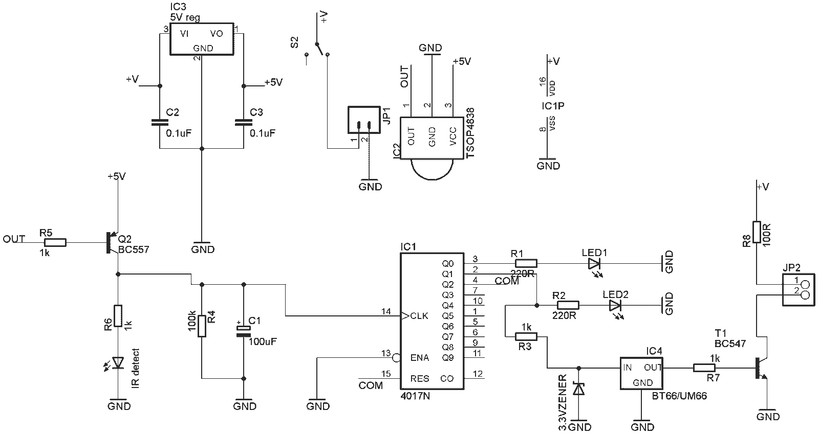
When you press an Infrared remote (a TV/VCD/DVD remote or a dedicated one) directing towards the remote bell, an infrared(IR) sensor TSOP4838 senses the IR signal. This signal with the help of a PNP transistor (BC557) charges the RC network(C1 and R4) and gives clock signal to the CD4017 chip. CD4017 then switches on its pin 2 (Q1) (until it receives the next IR signal) and drives the BT66 musical chip and with the help of BC547 transistor based amplifier and a music is played on the speaker.
Power supply: 6V to 9V DC
Watch the video below:
Schematic of the kit is given below:
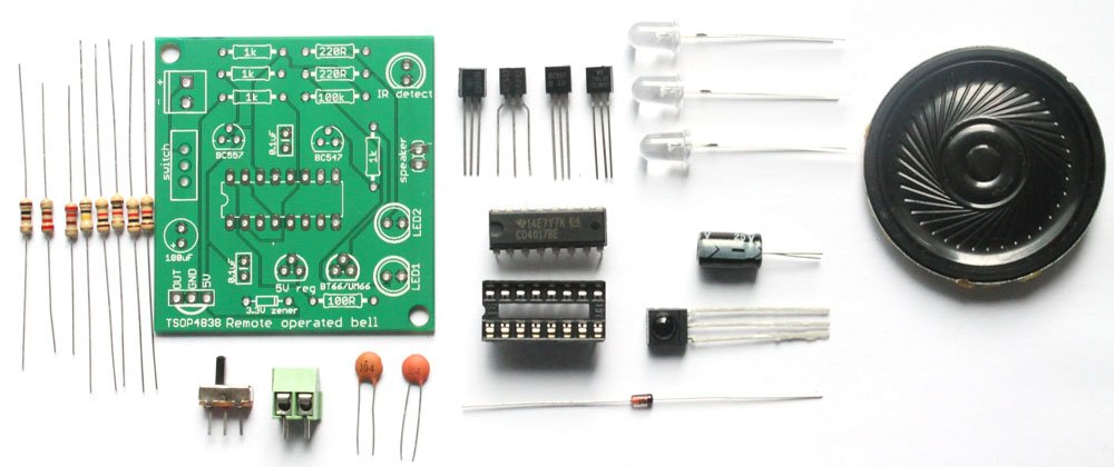
The kit package includes the following components:
- 1 x A bare PCB with silkscreen indicators- The PCB has been labeled properly so that you can solder the components easily just following the labels.
- 1 x IC1: CD4017: CD4017 is one of the versatile decade counter chips that is immensely used by electronics beginners and engineering students. You can search for several CD4017 based kits on google. The kit package also contains 16 pin IC socket for the chip.
- 1 x IC2: TSOP4838: TSOP is a popular infrared sensor that senses infrared signals with frequency 38KHz.
- 1 x IC3: TO-92 package 5V regulator IC.
- 1 x IC4: BT66/UM66 musical chip. This chip generates music. Read more about BT66/UM66.
- 1 x 3.3V zener diode: This zener diode regulator 3.3V supply to the UM66 or BT66 musical chip.
- 3 x Light emitting diodes (LED1, LED2 and IR detect): The LED labeled ‘IR detect’ switches on when the TSOP4838 sensor senses the infrared signal. LED1 is ON when the circuit is not playing music and LED2 is ON when the circuit is playing music. Both LEDs are never ON at the same time.
- 1 x Electrolytic capacitor (C1-100µF): This capacitor is used in the RC network for providing clock signal to the CD4017 IC.
- 2 x Ceramic capacitors (C2 and C3): These ceramic capacitors are used for filtering AC ripples and unwanted signals and regulate perfect 5V DC signal to the circuit.
- 2 x Transistors (BC547 and BC557): BC547 works as audio amplifier while the music is played and BC557 charges up the RC network of R4 and C1 and gives clock pulses to the CD4017 chip.
- 1 x 2 pin screw terminal: This screw terminal is used to connect 6V to 9V power supply.
- 1 x SPDT switch: Use this switch to switch ON/OFF the circuit.
- 1 x Mini speaker: It is a low power speaker for playing the music.
- 8x Resistors: There are altogether 8 resistors with four different values:
- 1K Ohm: Color code: Brown- Black- Red
- 100K Ohm: Color Code: Brown- Black- Yellow
- 1oo Ohm: Color code: Brown- Black- Brown
- 220 Ohm: Color code: Red- Red- Brown
If you do not know how to read resistors, see this tutorial
How to use the kit
You will need a 6V to 9V power supply(battery) to operate the kit. Connect a battery to the kit and press any switch of your remote control close to the kit, it simply starts playing a music.
To play: Direct your remote control towards the TSOP4838 Infrared sensor and press whichever remote key you like. LED2 remains ON and LED1 remains OFF when the music is played.
To stop: Press any key again, the circuit will stop playing the music. LED1 remains ON and LED2 remains OFF when the music is stopped.
Watch the video below:

🛠️ Dive into our collection of DIY Kits, 🔊 Audio Amplifiers, Digital Scoreboards, FM transmitters, and more!
🎶 Explore endless possibilities at our new store.


