Remote musical bell- Assembly tutorial
Remote operated musical bell- Assembly tutorial

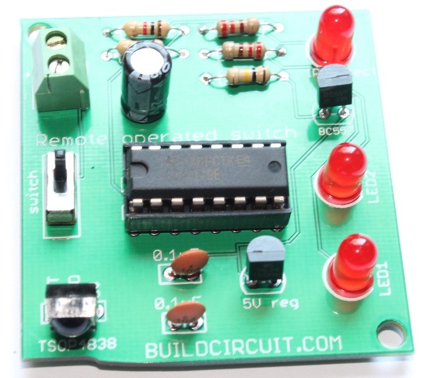
This kit package includes everything you need to make a remote operated musical bell. Assembly of this kit is very straightforward and all the components are through-hole. You can see the labels printed on the circuit board and assemble the components following those labels.

Step 1: Solder 4 pcs 1K ohm resistor. Color code of 1K resistor is Brown-Black- Red. Learn how to read resistor codes.

Step 2: Solder 220 Ohm resistors and 100K Ohm. Learn how to read resistor codes.
100K Ohm ![]()
220 Ohm ![]()
Step 3: Solder 0.1uF ceramic capacitor. The code for 0.1uF capacitor is 104.
![]()
Step 4: Solder BC547 and BC557 transistors

 BC557
BC557
Step 5: Solder 5V regulator (TO-92 package)


Step 6: Solder BT66/UM66 musical IC


Step 7: Solder 3.3V zener diode


Step 8: Solder 100 Ohm resistor. Learn how to read resistor codes.
100 Ohm resistor: ![]()

Step 9: Solder 16 pin DIL socket for CD4017 IC.


Step 10: Solder 5mm LED. This works as an indicator whenever the infrared sensor detects IR rays.


Step 11: Solder LED1 and LED2
Step 12: Solder 100uF electrolytic capacitor


Step 13: Solder SPDT switch


Step 14: Solder 2 pin screw terminal

Step 15: Solder TSOP4838 infrared sensor

Step 16: Solder speaker. Don’t care + and – pins of the speaker. You can connect it either way.


Step 17: Fix the CD4017 IC over the 16 pin DIL socket


Step 18: Connect a 9V battery and use the kit. The kit works with ANY kind of remote control.


Watch the output:


🛠️ Dive into our collection of DIY Kits, 🔊 Audio Amplifiers, Digital Scoreboards, FM transmitters, and more!
🎶 Explore endless possibilities at our new store.