


Ultrasonic range finder on breadboard using Arduino, DYP-ME007 and NE555

Ultrasonic means the frequency of the sonic (sound) pulse is above the human hearing range. The highest frequency that is detectable by the human ear is approximately 20 KHz. In this project, I have used DYP-ME007 Ultrasonic range finder(URF). I bought this Ultrasonic range finder from Ebay.com and this is NOT a good experiment module. However, you can use it to understand and test how an ultrasonic range finder works. The performance of this URF is not as good as ping))). The important facts regarding this sensor is given below:
Specifications:
Working Voltage : 5V(DC)
Working Current : max 15 ma
Working frequency : 40HZ
Output Signal : 0-5V (Output high when obstacle in range)
Sentry Angle : max 15 degree
Sentry Distance : 2cm – 500cm
High-accuracy : 0.3cm
Input trigger signal : 10us TTL impulse
Echo signal : output TTL PWL signal
Size : 45*20*15mm
Pins :
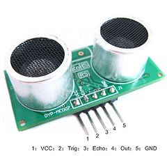

Usage:
Supply module with 5V, the output will be 5V while obstacle is within range otherwise it outputs 0V.
Note : the module should be inserted in the circuit before giving power which avoids chances of misoperation ;if it does not work, power again.
Module Working Principle:
(1) IO trigger Pin(2) should be given HIGH LEVEL pulses of at least 10us.
(2) The module then starts sending ultrasonic sound of 40khz frequency and receives the pulses if there is any obstacle nearby.
(3) If there is signals returning, then the ECHO pin output high level pulses and the following formula is to used to calculate the distance of obstacle.
Test distance = (high level time * sound velocity ) / 2
where sound velocity= 340m/sec
How to send pulses of at least 10us?
– Circuit given below is 555 IC based astable multivibrator, this gives high level pulses at a period of 30us. The output pin 3 of 555 has been connected to trigger pin and the echo pin of URF has been taken to DIG 9 of Atmega328 (Pin 15 on chip)

MAKING STEPS
First of all, make an Arduino Programmer on breadboard using FT232RL breakout board. It is very easy and you can get the tutorial on this link: CLICK HERE.You can also make the project using Arduino board, but if you want to make it independent of Arduino board, I recommend you to make the project on breadboard. The main advantage making on breadboard is that you can later solder the project on PCB.
The basic direction for making Arduino programmer can be achieved from the following picture.

Then, fix an 16×2 LCD with the programmer. I guess that you can see the used pins from the picture given below. You can also get tutorial here: CLICK HERE
ATmega328 and 16×2 connection-
Pin no. on Chip Pin no. on LCD
4 (DIG 2) 14
5(DIG 3) 13
6(DIG 4) 12
11(DIG 5) 11
12(DIG 6) 6
13(DIG 7) 4


Now, make the 555 based multivibrator
– Keep IC on breadboard; short pin 1 to GND; short Pin 2 to 6; insert 1M resistor across Pin 6 and 7.

– Insert 1K resistor across Pin 7 and Vcc(Power).

– Short Pin 4 and 8 and connect Pin 8 to Vcc(Power).

– Insert 22p capacitor across pin 2 and 1; and 0.1uF capacitor across Pin 5 and GND.

Now the 555 astable configuration is ready.

Then Insert URF on the breadboard.
After insertion on breadboard, it must look like this:

Close up


Finally the whole assembly would look like this.


DOWNLOAD THE DESCRIPTION OF THE MODULE
Related experiment: Ultrasonic range finder using HC-SR04
🛠️ Dive into our collection of DIY Kits, 🔊 Audio Amplifiers, Digital Scoreboards, FM transmitters, and more!
🎶 Explore endless possibilities at our new store.

can u help me in making a project using above components
i want to make a project for blind person navigation
blind person will wear that circuit or project in his hand or arm , head , then wen any obstacle come in front of Ultrasonic range finder SRF04 they sends signal to PIC controller n PIC controller vibrates the vibration motors attached to any particular area where the circuit is attached so a blind can understand that he or her is close to any obstacle , n the closer the obstacle the more vibration produce, means vibration should be inversely proportional to distance between person and obstacle
Hi,
thanks for expressing your interest. You have a great idea but I am sorry to say that I cannot help you with PIC. My site is about arduino and I can only work with arduino. I strongly recommend you to use Ping))) module to work on your idea rather than SRF04 module because it is better than SRF04.
For the reason that the admin of this site is working, no uncertainty very quickly it will be well-known,
due to its quality contents.
I am always searching online for ideas that can aid me.
Thanks!
thanks for this I was loking for something like this, now I’m gonna use it in my project.
Throughout the awesome scheme of things you’ll receive a B+ for hard work. Exactly where you misplaced everybody ended up being in your particulars. You know, they say, the devil is in the details… And it could not be more correct in this article. Having said that, let me reveal to you precisely what did work. Your article (parts of it) can be extremely convincing and that is most likely why I am taking the effort to comment. I do not make it a regular habit of doing that. Secondly, although I can notice the leaps in logic you come up with, I am not confident of how you appear to connect the points that make the actual conclusion. For now I shall subscribe to your issue however trust in the foreseeable future you connect your facts better.