


Basic remote tester

Description: This circuit can be used for testing your TV, DVD, VCD, etc. remote control. This is the fundamental module for making infrared based object counter. This project has been derived from “Remote tester project” .
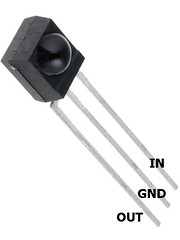
According to the datasheet of TSOP4838, the input voltage to IR sensor should be 3V-5V. When the sensor gets infrared signal, the voltage at its VO pin drops and that triggers the BC557 transistor. At each trigger signal, BC557 glows the LED. Thus, you can see the response of your remote control signal.
WATCH THE VIDEO:
In the schematic below, for TSOP 4838, V1 is INPUT and VO is OUTPUT.
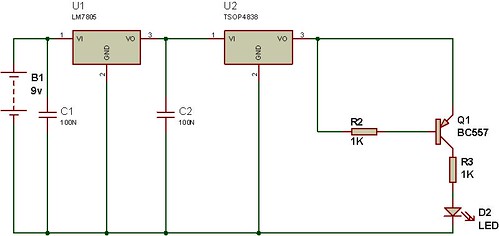

FRITZING application does not have TSOP4838, so, I used the available infrared module. The available module does not look like the one we use in this experiment.
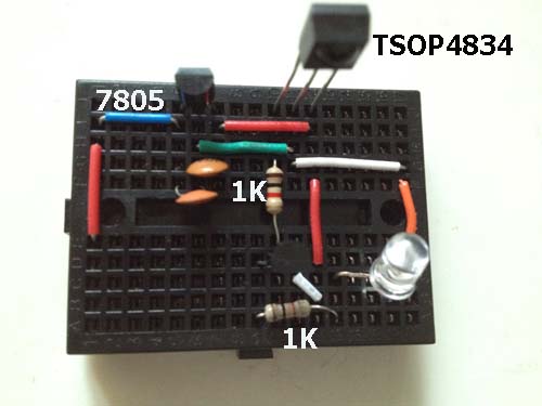
In real, the experiment set up looks like this:
WATCH THE VIDEO:
🛠️ Dive into our collection of DIY Kits, 🔊 Audio Amplifiers, Digital Scoreboards, FM transmitters, and more!
🎶 Explore endless possibilities at our new store.


Hey sagar
i have used TSOP1738….but the circuit is not working….the L.E.D. is continously being litted up dimly…..any suggestions?!??
Sir i need project circuit daigram sir..so send me
hi! my project worked perfectly for 10 seconds then i dnt knw what happened? the led stopped blinking when i pressed the power button of my remote! the ICs are being heated up! any way to reduce the heat? if i use heat sink then where should i connect it? on the breaadboard! please tell.
Thanks!
I think you connected the IR sensor incorrectly. I have done IR experiments several times, but I have never faced such problems. Please check your connections.
Hi sir, thank you for the nice tutorial! I just want to get clear, what does C1 and C2 mean? does it mean, capacitor? and what does U1 and U2 mean?
also, can i use this kind of circuits in a white breadboard? and in your black breadboard, where is the positive and negative in there? could you please post a tutorial of this using a white breadboard? if possible.Thanks man.
for remote checking you can also use your mobile camera,
the easiest way of checking
Can we use Buzzer instead of LED?
i can’t see the values of capacitor clearly , is it 100 micro or nano F ?
can i use any tv remote …??
plz reply urgent need to do my project with in 2 days.
Thanks.
Should the emitter of the BC557 be going to the +5V instead of the IR receiver output in the schematic above? Seems that way in the breadboard component layout and on my own test here it works that way.
Can I use a normal ir receiver instead of TSOP4838????