Amarino based Sensor Graph with Custom Bluetooth ID and LED controller

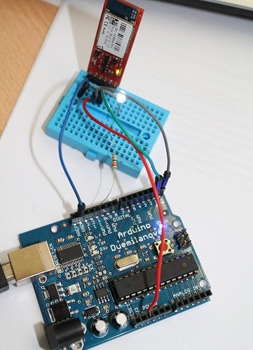
In this project, you can control an LED and see sensor graph simultaneously. For your convenience, I have used a simple light sensor circuit. The resistance of the photo resistor varies with the amount of light falling on it. The amount of light is varied with LED controller and the sensor data variation can be seen on the Sensor Graph.

Amarino project- Arduino and Android based light sensor

With this project/application, you can make a light sensor dependent lamp. You can make a light sensor or dark sensor with this application.

The light sensor of your Android smart phone senses ambient light present in your room and sends commands to Arduino board. Your Arduino program determines the behaviour of the LED, whether it should glow bright or dim. You can also see the light sensor data on the smart phone interface. (more…)

Infrared sensor with PWM

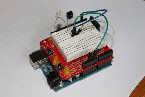
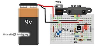
Description: In this project, Arduino first encodes the remote signals and decodes them to control LED brightness. First of all, connect the Infrared sensor as shown in the picture below. Then, press keys 0 through 4; Arduino stores the values for keys 0 through 4 and when the sketch runs, key 0 turns off the LED and the brightness of the LED increases in steps when keys 1 through 4 are pressed. (more…)

Experiments with 741- Operational amplifier

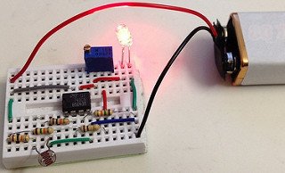
Description: This versatile 741 operational amplifier module can be used for making a dark detector using an LDR, a photo transistor and a photo diode. The amplifier has been configured in inverting mode. It compares the change in voltage at pin 2 with the reference voltage at pin 3 and gives output at pin 6 accordingly.  A general calculation and working of similar project has been explained on buildcircuit.com.  CLICK HERE for the project. (more…)

RC module

Description: An RC circuit is used to introduce time delay in circuits. A combination of resistor and capacitor gives a time constant.

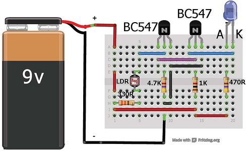
The following circuit shows a basic RC circuit. In the figure C1(100uF) works as a storage capacitor. When you press the switch, the capacitor charges quickly and provides base current to the transistor Q1, that results in collector current and that glows the LED D1.. The resistance R2(1K) provides a time constant of around 10seconds. After 10seconds, the base current is not enough for driving the transistor, so the LED also goes off. (more…)

Multivibrator module

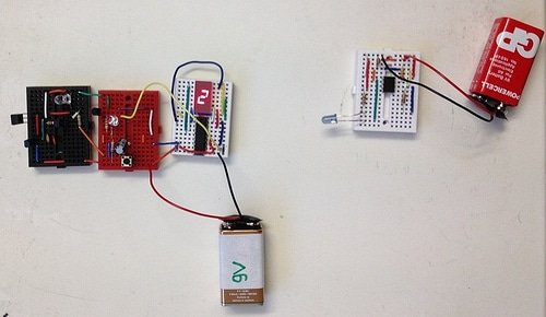
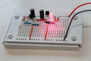
Description: A multivibrator has identical components(capacitors, transistors and resistors) arranged on the left and right hand sides that can be used to implement a variety of simple two-state systems such as oscillators, timers and flip-flops. In a multivibrator circuit, increasing the value of the two electrolytic capacitors increases the time each LED remains on/off.  (more…)

MINIBREAD

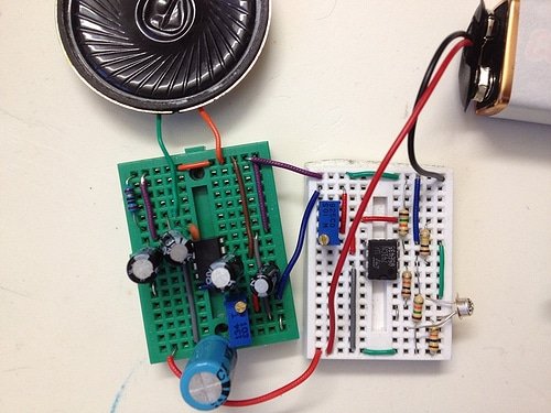
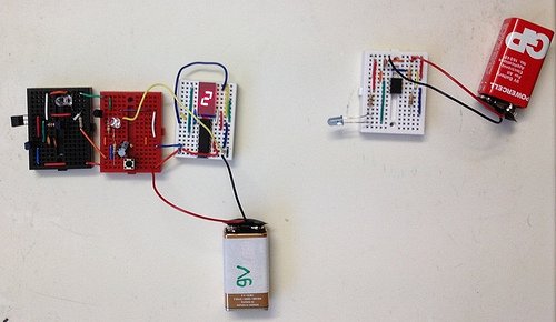
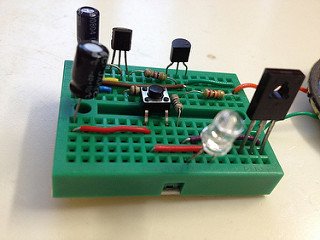
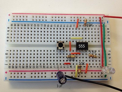
MINIBREAD is a simple technique of making electronic projects on mini breadboard. I have published basic electronic projects keeping electronic amateurs and students in mind. (more…)

Search for products

Back to Top
Product has been added to your cart