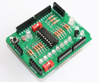
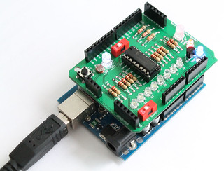
Amarino shield- CD4094 control with Arduino- WITHOUT SMART PHONE
This is the first experiment for Amarino shield. If you do not know anything about Amarino toolkit or this shield please click on the following links:
You can get a list of other experiments at the end of this post.
This experiment has been derived from HEF4794_- Arduino_ Experiment.
This example makes the use of an LED Driver in order to control an almost endless amount of LEDs with only 4 Arduino pins. In this experiment, we use the CD4094 chip. Here, you can get the original version of this experiment: http://www.arduino.cc/en/Tutorial/LEDDriver . The Arduino team has used HEF4794.
An LED Driver has a shift register embedded that will take data in serial format and transfer it to parallel. It is possible to daisy chain this chip increasing the total amount of LEDs by 8 each time. You need to refer to datasheet for connecting more CD4094.
The code example you see here is taking a value stored in the variable dato and showing it as a decoded binary number. E.g. if dato is 1, only the first LED will light up; if dato is 255 all the LEDs will light up.
NOTE: Switch ON the IC1 -1 P DIP switch. If the switch is off, the 10pcs of LEDs connected to CD4094 will not work.
Arduino Sketch: LINK
Related tutorials:
- About Amarino toolkit
- About Amarino shield
- Flickr Images
- Experiment 1– Basic control over CD4094 without Android phone and serial emulator application
- Experiment 2- CD4094 control using Android phone and Amarino shield
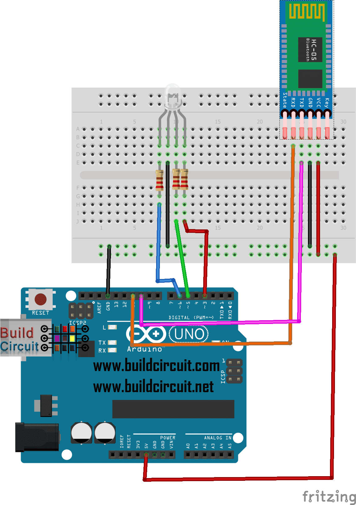
- Experiment 3- Amarino experiment- RGB Lamp
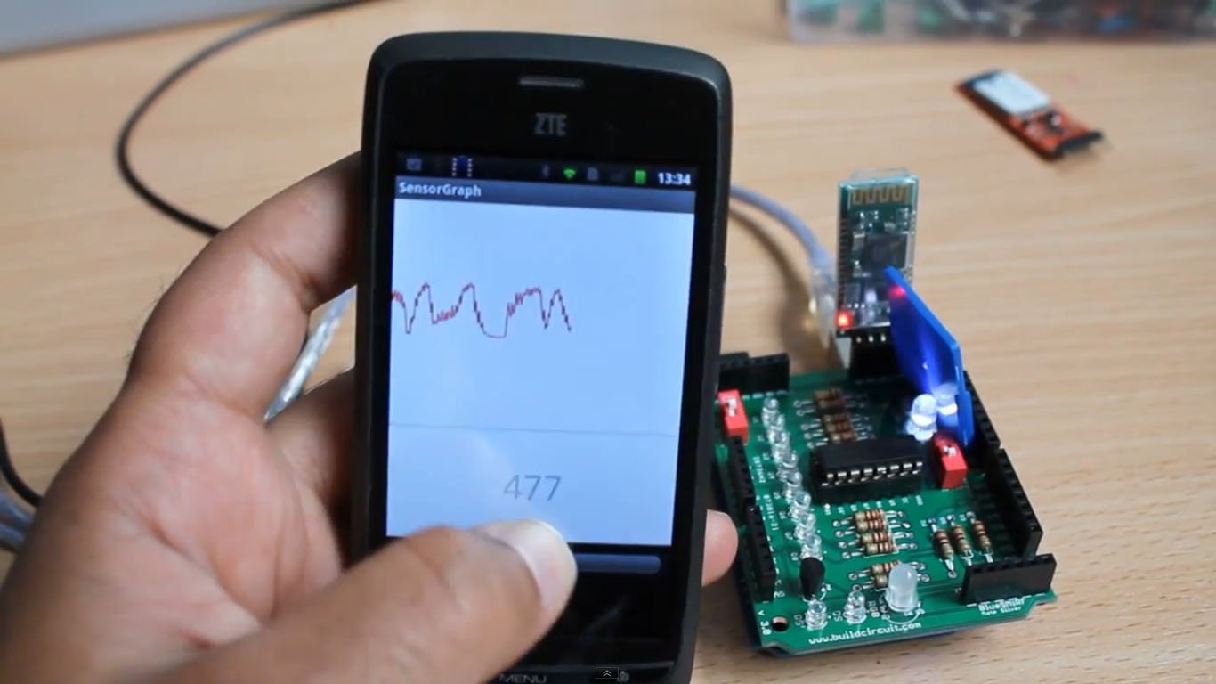
- Experiment 4- Amarino experiment- Sensor Graph with LED Controller
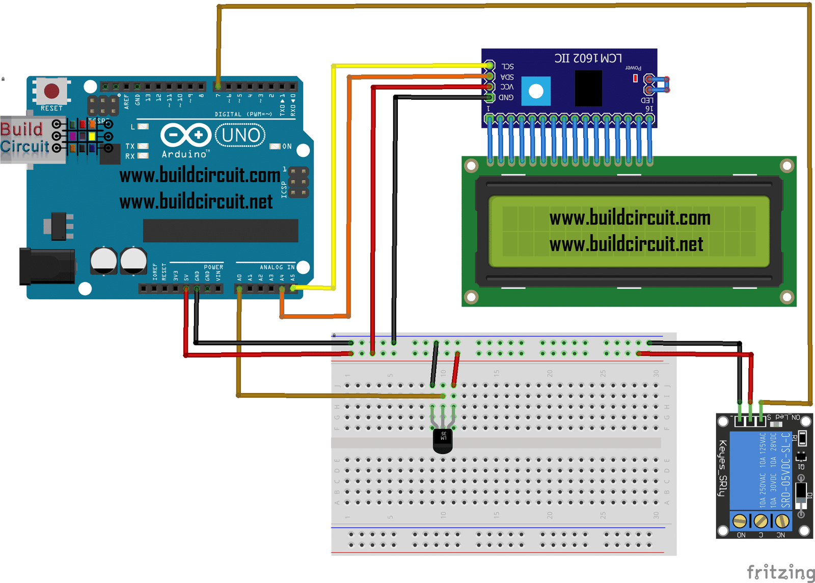
- Experiment 5- Amarino experiment- LM35 based temperature sensor with LED controller
- Amarino Shield 3.0 Schematic
- Assembly tutorial
- Buy the shield
You can purchase this versatile Amarino shield at buildcircuit.net and Etsy. The store is owned and operated by the team which operates buildcircuit.com.
![]()

🛠️ Dive into our collection of DIY Kits, 🔊 Audio Amplifiers, Digital Scoreboards, FM transmitters, and more!
🎶 Explore endless possibilities at our new store.