


DIY KIT 47- NE555 based Traffic Signal Light Simulator
The description has been copied from eBay, so, really sorry for the bad English.
When S1 is pressed, U1 NE555 pin no. 2 and 4 will get low level at the same time and NE555’s pin no.3 will also be at low level, 7 pin discharges and 6 pin also gets low level.
If S1 is released, 4 pin will become high level, then pins 2 and 6 will get low level. Therefore, U1 NE555 output pin no. 3 will be high, Q2 is connected to it and the 4pcs LEDs on the left group will turn on. At the same time, Q3 is connected, U2 NE555 outputs low level and the LEDs on the right group will be off.
Work Status:
The controller can control the on/off of the red lamp, green lamp and yellow lamp from four directions.
When the red lamp on the east and west is on, the lamp on the south and north is on, and the cars and passers-by can go across the street;
when the lamp on the east and west is transforming into green from red and the lamp on the south and north is transforming into red from green, the yellow lamp will flash.
A great explanation of the kit is here:
Parameter:
| NO. | Parameter | Value |
| 1 | Name | Traffic light DIY Kit |
| 2 | Operating Voltage | DC 4.5-5V |
| 3 | PCB Size | 90*46mm |
Component List:
| NO. | Component Name | PCB Marker | Parameter | QTY |
| 1 | Electrolytic Capacitor | C1,C2 | 22uF/10-50V | 2 |
| 2 | Electrolytic Capacitor | C3,C4 | 10uF/10-50V | 2 |
| 3 | Electrolytic Capacitor | C5 | 1uF/10-50V | 1 |
| 4 | Rectifier diode | D1-D4 | 1N4001 | 4 |
| 5 | 2*5*7 LED | L3,L4,L7,L8 | Red | 4 |
| 6 | 2*5*7 LED | L1,L2,L5,L6 | Green | 4 |
| 7 | 2*5*7 LED | L9-L12 | Yellow | 4 |
| 8 | Transistor | Q1-Q5 | S8050 | 5 |
| 9 | Metal Film Resistor | R1,R2,R8,R14,R16 | 10K | 5 |
| 10 | Metal Film Resistor | R3,R4,R15 | 510K | 3 |
| 11 | Metal Film Resistor | R5,R6 | 1M | 2 |
| 12 | Metal Film Resistor | R7 | 100ohm | 1 |
| 13 | Metal Film Resistor | R9,R10,R11,R12,R13 | 1K | 5 |
| 14 | Button | S1 | 6*6*5mm | 1 |
| 15 | NE555 | U1-U3 | DIP-8 | 3 |
| 16 | CD4011 | U4 | DIP-14 | 1 |
| 17 | PCB | 90*46mm | 1 |
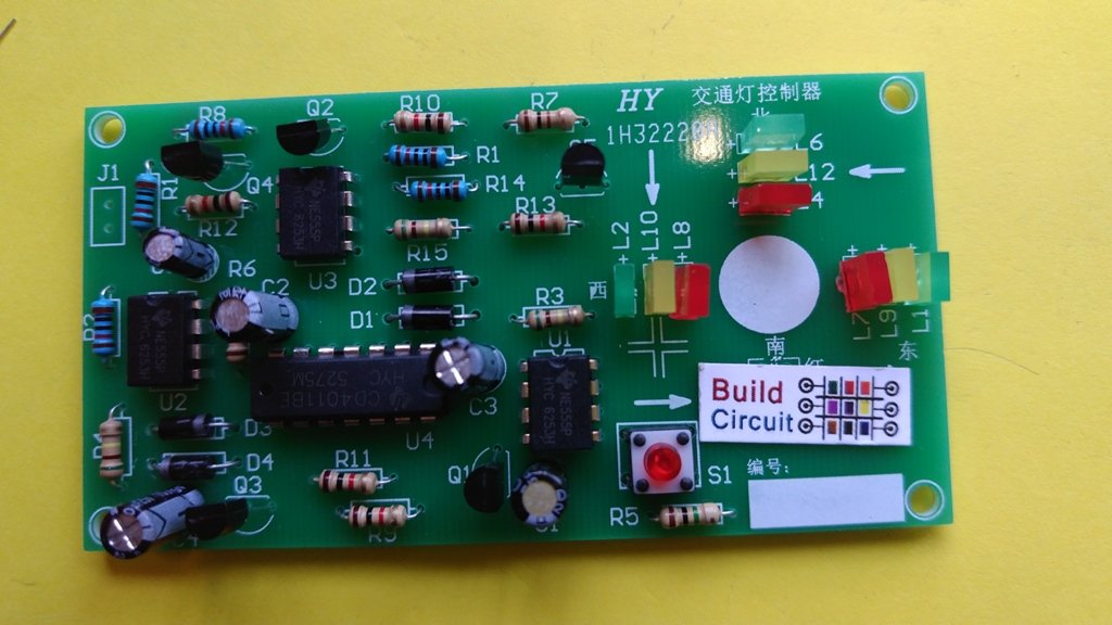
See all the images below to get the idea for assembling the kit. You can see the images on Flickr also.


More images of the kit


🛠️ Dive into our collection of DIY Kits, 🔊 Audio Amplifiers, Digital Scoreboards, FM transmitters, and more!
🎶 Explore endless possibilities at our new store.

