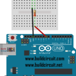
What is a voltage divider circuit
A voltage divider network is a fundamental electronic circuit used to divide a voltage into smaller fractions. It consists of two or more resistors connected in series or in a string, which create intermediate voltage points between the supply voltage and ground. Voltage dividers are commonly used for various purposes in electronics, including setting reference voltages, biasing transistors, and creating level-shifting circuits.
The basic principle of a voltage divider is based on Ohm’s law, which states that the current through a resistor is directly proportional to the voltage across it and inversely proportional to its resistance. In a voltage divider, the ratio of the resistance values determines how the input voltage is divided between the resistors.
Mathematical Formulation:
The output voltage (Vout) of a voltage divider can be calculated using the formula:
Vout=Vin×R2R1+R2
Where:
- Vin is the input voltage applied across the voltage divider.
- R1 and R2 are the resistance values of the two resistors in the divider.
Applications of Voltage Divider Networks:
- Voltage Level Shifting: Voltage dividers can shift the voltage level of a signal. For example, they are used in resistor networks to adjust signal levels for compatibility between different parts of a circuit.
- Reference Voltage Generation: Voltage dividers are used to generate reference voltages for analog-to-digital converters (ADCs) and digital-to-analog converters (DACs).
- Biasing Transistors: Voltage dividers are commonly used in transistor biasing circuits to set the base or gate voltage of the transistor.
- Sensors and Measurement: Voltage dividers are used in sensor circuits to measure changes in resistance, capacitance, or other properties.
- Potentiometers: A potentiometer is a variable resistor used in voltage divider configurations to provide adjustable voltage outputs.
- Signal Attenuation: Voltage dividers are used to attenuate or reduce the amplitude of a signal while maintaining its shape.
- Zener Diode Voltage Regulation: Voltage dividers in combination with Zener diodes can be used to regulate voltage levels.
- Low-Power Applications: Voltage dividers are often used to create low-power biasing networks in energy-efficient circuits.
Considerations:
While voltage dividers are versatile and widely used, there are a few considerations to keep in mind:
- Voltage dividers are sensitive to changes in load impedance. A significant load can affect the accuracy of the divided voltage.
- Current flowing through the divider results in power dissipation in the resistors. Ensure that the power rating of the resistors is sufficient to handle the current and prevent overheating.
In summary, voltage divider networks are a fundamental and versatile circuit arrangement that finds application in a wide range of electronic systems and components. Understanding how to design and use voltage dividers is essential for effective circuit design and analysis.


