How to use DS1307 Real time clock module with Arduino

Most of the microcontrollers are time-agnostic, meaning they are unaware of the time around them, but it doesn’t matter as most experiments do not require it. But, there are several experiments that require the actual time. For example, most of the experiments related to data-logging require time.
The following Real time clock (RTC) module can add actual time value to your data-logging experiments.
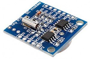
![]()
For this article we will be discussing and using a RTC Module available at buildcircuit.net because it incorporates everything you need to make it work, including a backup battery good for a minimum of 3 years. It comes with the time preset, but you can easily reset it and configure to your own time.
About DS1307
Read about I2C at tronixstuff.com (highly recommended)
The DS1307 is actually a very simple I2C chip. It just gives you back 7 bytes of information that is the time. So, all we need to do is receive it and converts it to decimal. The DS1307 encodes all the data in “Binary Coded Decimal” or BCD. BCD is just a way to encode numbers, and works by encoding each digit in 4 digits of binary… like so:
157 = 0001 0101 0111
1 = 0001
5 = 0101
7 = 0111
Normally you would say that 157 = 10011101. But that is 157, BCD encodes each digit separately. 1, 5, 7 not 157. hence 0001, 0101, 0111 not 10011101.
Ok, now that we know we will be receiving the data as BCD, we just need a way to convert that to decimal. Luckily, John Boxall over at TronixStuff (incredibly awesome site) has a pretty simple function to do that for us.
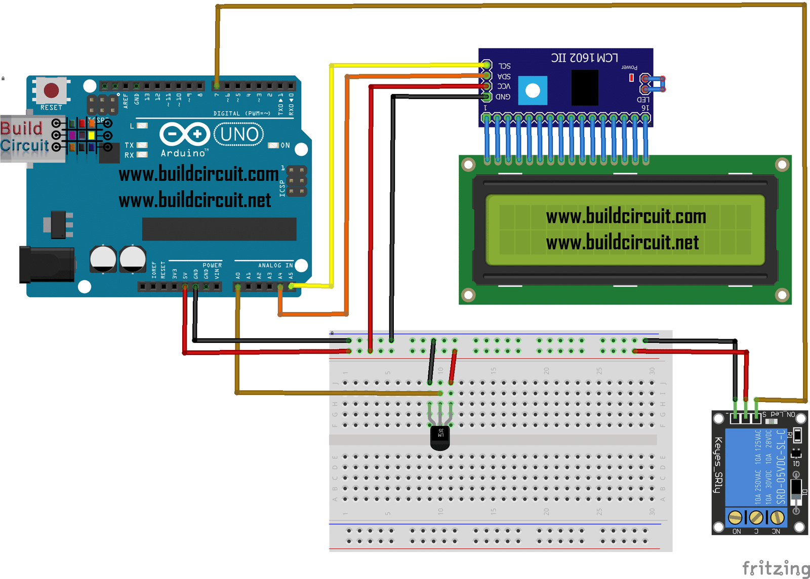
Connecting the module to Arduino:
Because the DS1307 is an I2C device (I2C is a 2-wire serial connection), you just need to connect the SDA (Data) and SCL (Clock) lines to your Arduino for communication. On your Arduino (all boards but the mega) SDA is on analog pin 4, and SCL is on analog pin 5. On an Arduino mega, SDA is digital 20, and SCL is digital 21.
You can buy the real time clock module at www.buildcircuit.net. The store is owned and operated by BuildCircuit Team.
![]()
Sketch:
If you intend to use the clock to set alarms and trigger events based on time, then you should take a look at Lady Ada’s library for this. It’s more advanced, and allows you to make alarms, and check how much time is left and so on.
The following source codes have been copied from bildr.org. The code can be used for testing the module. It simply displays the set time and date.
LINK
RUNNING THE FOLLOWING CODE WILL RESET THE TIME You will need to set the correct time in the setDateTime function. Also because the time is set at setup(), it will set the time to that value every time the Arduino restarts. So after you have set it, either upload the above code, or comment out setDateTime from setup, and re-upload the sketch. If you need to change the time a bunch, or just make it easy, you could set it up so you can change it via the serial terminal. That could be cool ! LINK
MORE SIMPLE CODE FROM ADAFRUIT.COM
Adafruit.com also sells its own model of real time clock module. They have an excellent library for the module. DOWNLOAD THE LIBRARY.
The library and source codes available are excellent for data-logging experiments.
In this experiment, the sketch reads the time from the RTC once a second. You will see what happens if you remove the battery and replace it since that causes the RTC to halt. Load up the following sketch (which is also found in Examples→RTClib→ds1307) and upload it to your Arduino with the datalogger(data-logging components) shield on!
🛠️ Dive into our collection of DIY Kits, 🔊 Audio Amplifiers, Digital Scoreboards, FM transmitters, and more!
🎶 Explore endless possibilities at our new store.