Scoreduino-B Arduino based controller for digital scoreboards

Watch the video of Scoreduino-B
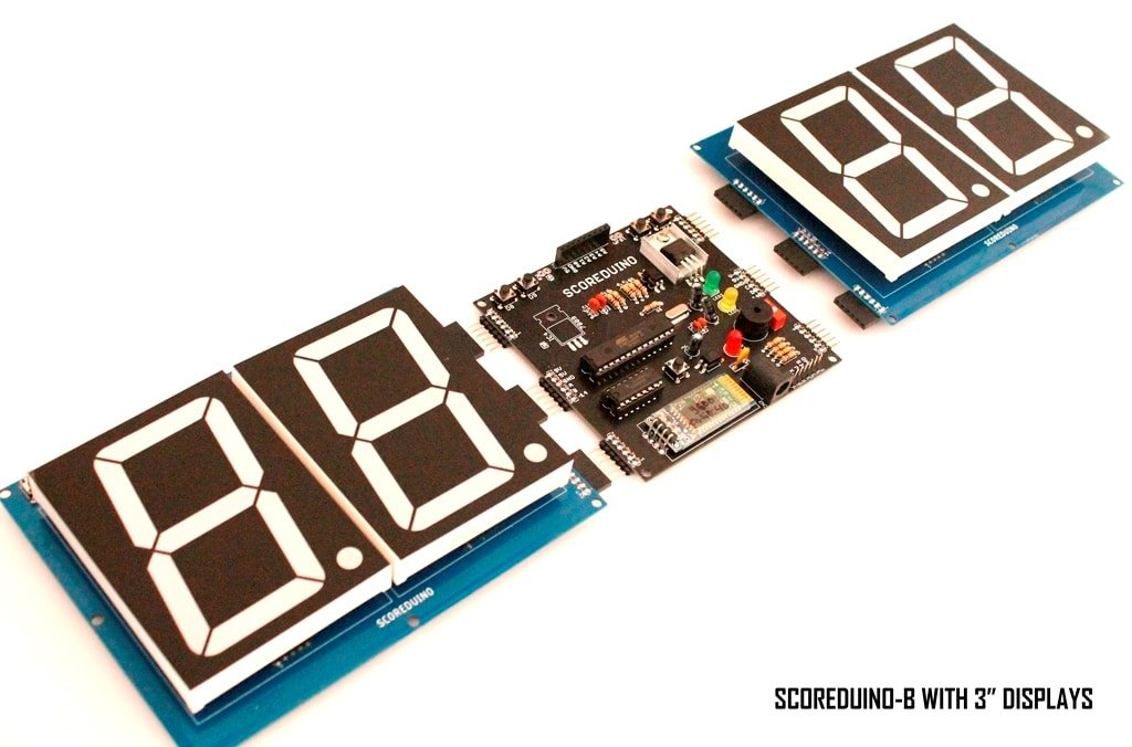
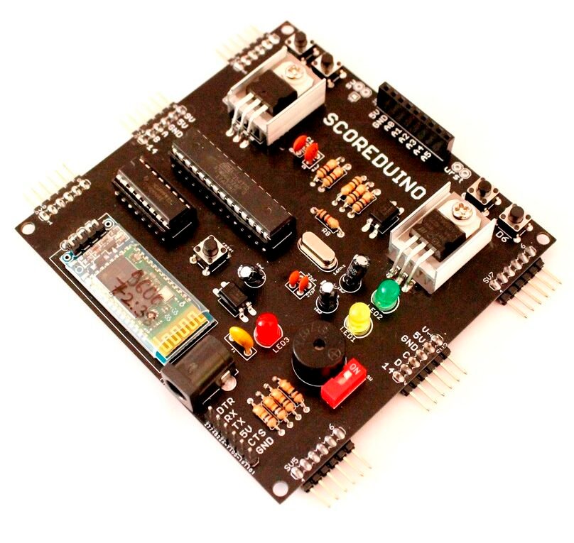
The ‘SCOREDUINO-B’ module works as a basic controller for 2.3″, 3″, 4″, and 5″- 4 digits (2 on each side) scoreboards. It has 4 switches for up and down commands for each set of 2 displays.
Other features:
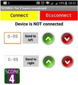
- It has a Bluetooth module that communicates with the SCORE4 module of the Scoreduino app and control signals can be sent to Scoreduino-B via Bluetooth
- It has a header for an RF module which makes it capable of receiving up/down control signals from RF remote control.
- Scoreduino-B is programmable like any other Arduinos. It requires an FTDI basic breakout board.
- The outputs of Scoreduino-B are inverted using CD4049.
- Designed to work with 2.3″, 3″, 4″ and 5″ scoreboards.
How does it work?
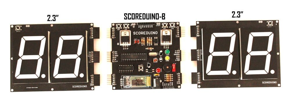
SCOREDUINO-B is designed to work with 2 sets of 2 digits up-down counter. This controller module fits into the female headers of the 2 digits counters on each side. It works with the SCORE4 app. Users can send specific numbers to each set of displays. The communication medium is either Bluetooth or RF or manual control.
An example:
When a user sends 15 to one of the displays, the Scoreduino-B sends up count pulses 15 times to count from 1 to 15, and finally, it stops at 15. All the up-down counters and scoreboards have been designed in that way.
These are the pins on the Scoreduino-B board:
On the left side:
- 9V: This is to power up RED colored 2.3″ displays. We get this voltage from the voltage regulator LM78XX.
- 5V: 5V is used for CD4511 and 74LS192 on the left side
- GND: GND of Scoreduino-B connects with the GND of 2 digits up/down counter
- A: Send pulse from Scoreduino-B via this pin in order to count UP
- B: Send pulse from Scoreduino-B via this pin in order to count down
- 14: Reset pin. Send pulse to reset the count.
On the right side:
- V: V depends upon the color of the displays used on the right side. For example, GREEN colored 2.3″ display needs 12V. This is the default supply voltage.
- 5V: 5V is used for CD4511 and 74LS192 on the right side
- GND: GND of Scoreduino-B connects with the GND of 2 digits up/down counter
- C: Send pulse from Scoreduino-B via this pin in order to count UP
- D: Send pulse from Scoreduino-B via this pin in order to count down
- 14: Reset pin. Send pulse to reset the count.
Components used:
- 1 x PCB
- 6 x 6 pin male header angle
- 1 x 6 pin male header for programming
- 1 x 9 pin female header- to be changed in the next version to make it 4CH only.
- 5 x tactile switches
- 2 x heat sink set
- 1 x LM7805
- 1 x LM7809
- 2 x 22pF capacitor
- 1 x 16Mhz oscillator
- 3 x 10uF
- 2 x PC817
- 5 x 10K
- 5 x 1K
- 3 x 5mm LED (RED Green and BLUE)
- 1 x 1P DIP switch
- 1 x buzzer
- 1 x DC barrel
- 1 x resettable fuse
- 1 x Bluetooth module
- 1 x 16 pin DIL socket
- 1 x 28 pin DIL socket
- 1 x Atmega328P
- 1 x CD4049
See all the images on Flickr
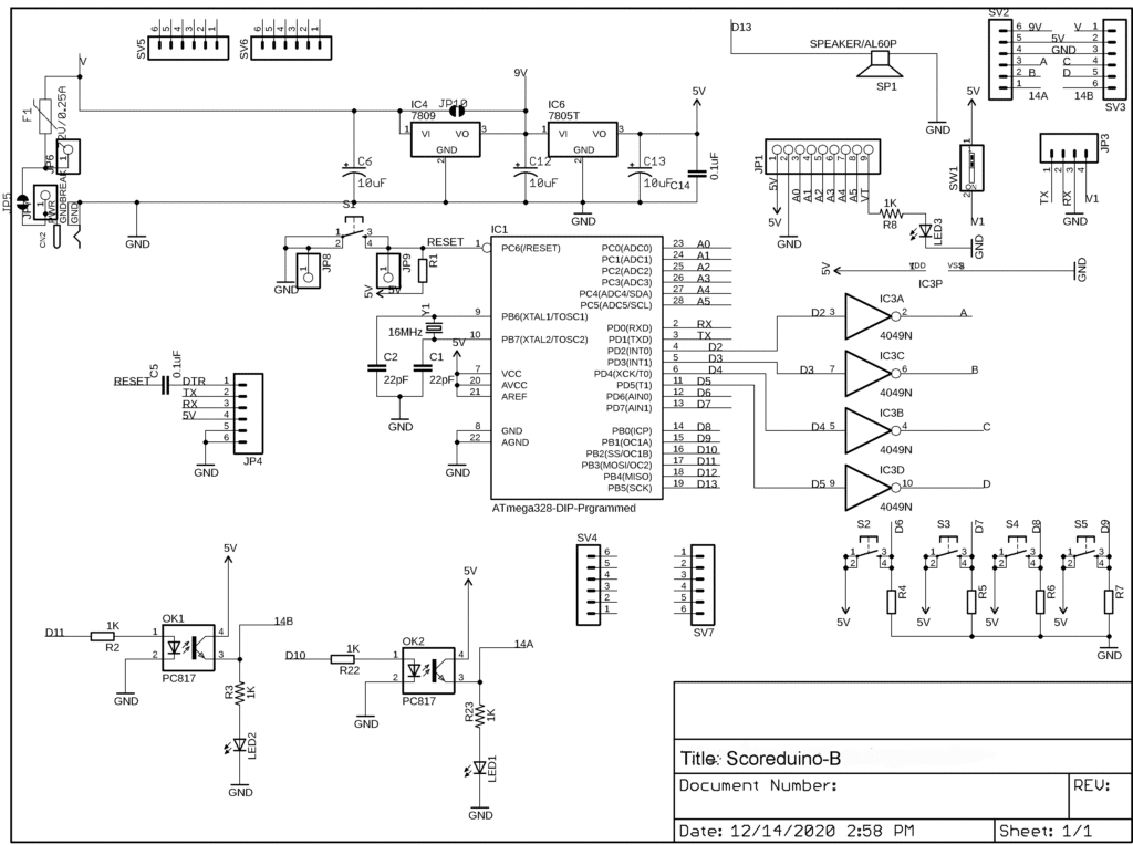
The Schematic:
This is how we use Scoreduino-B:
It works with SCORE4 module of Scoreduino app.


