
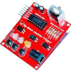
‘Scoreduino-A’ Trigger Module For Up and Down Counter Drivers
- Sorry, this product cannot be purchased.


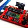

- Arduino based digital controller for up down counters and drivers
- Programmable with FTDI basic breakout board.
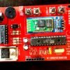
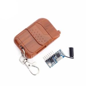
- Comes with a Bluetooth module and RF remote control.
- Scoreduino-A communicates with display drivers via Bluetooth or RF signals.
- It has switches for up, down, and reset commands
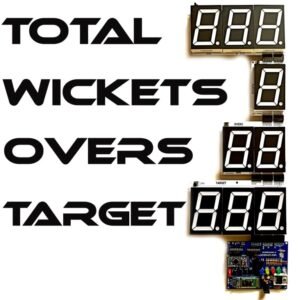
- Works with SCORE1, SCORE2, and SCORE3 modules of Scoreduino app
- Send specific numbers to displays. For example, if send 387 from the app, the displays will show the exact number.
Description
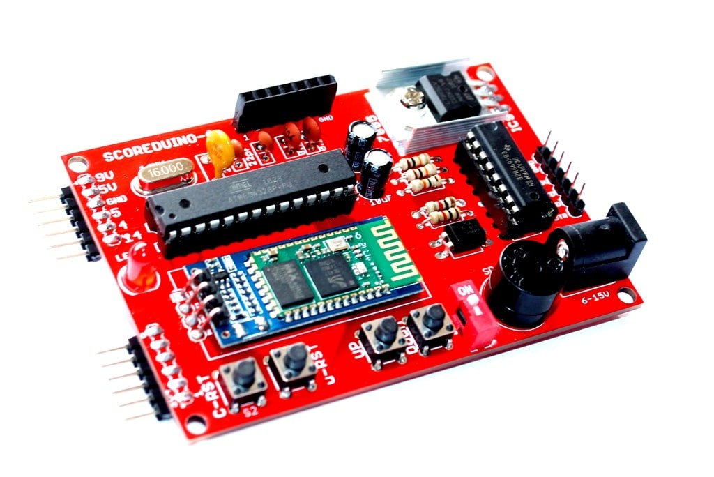
The video will show a different SCOREDUINO-A module. Both are electronically same, just the look is different.
It works with RF remote control and SCORE1, SCORE2 and SCORE3 modules of Scoreduino app.

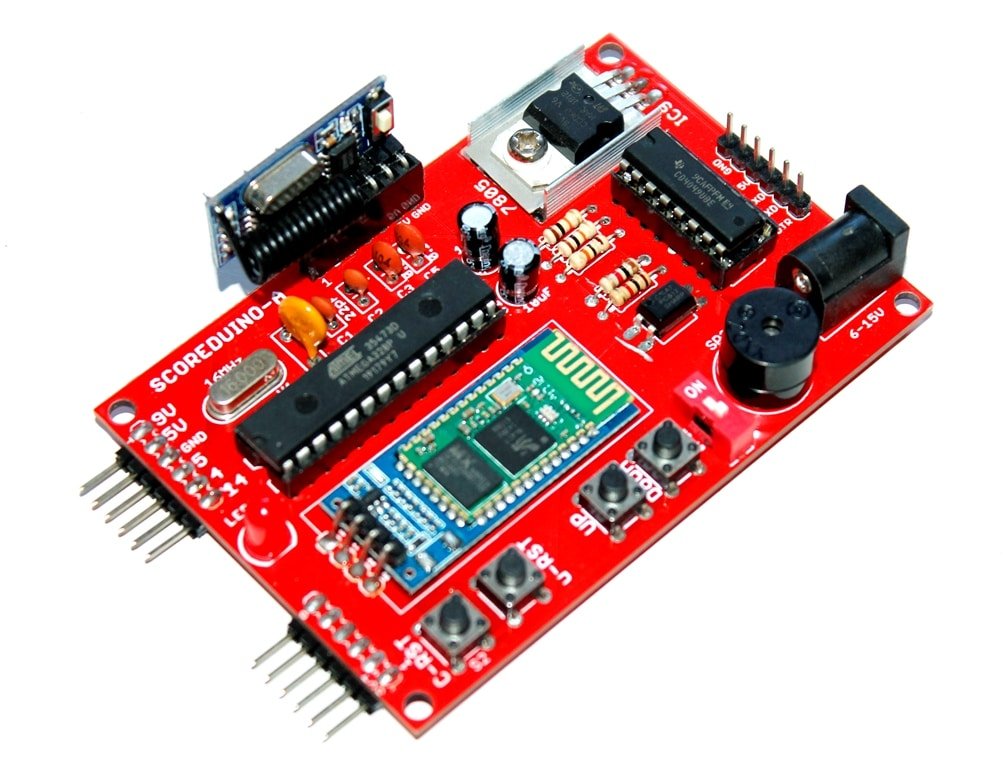
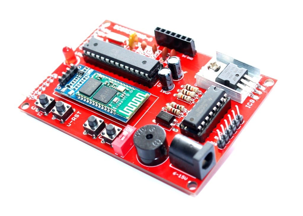
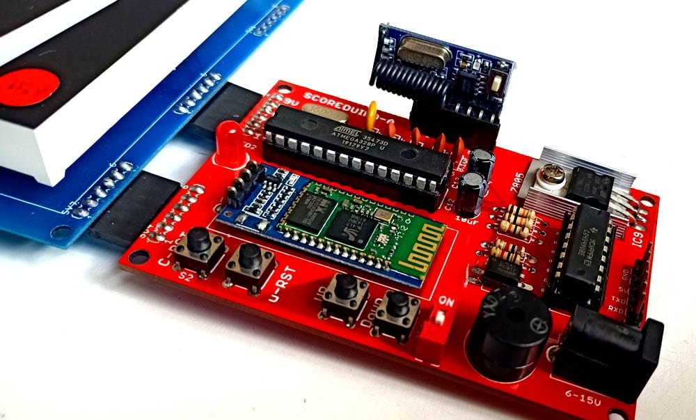
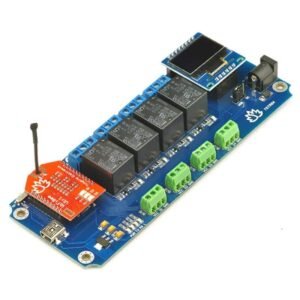
The ‘SCOREDUINO-A’ module works as a basic controller for up and down counters or seven-segment display drivers. It has 3 switches for up, down, and reset signals. Up switch increases the count and down switch decreases the count and the reset switch resets the count to zero.
Other features:
- It has a Bluetooth module that communicates with the Scoreduino app and control signals can be sent to the Scoreduino devices from the app.
- It has a header for an RF module which makes it capable of receiving control signals from RF remote control.
Scoreduino is programmable like any other Arduinos. It requires an FTDI basic breakout board.
How does it work?
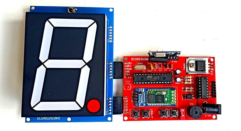
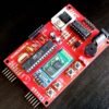
All seven segment display drivers are designed in such a way that this ‘Scoreduino-A’ module fits into the female headers of the drivers. The UP, DOWN and RESET pins of the trigger module connect to pins 5, 4, and 14 respectively of the 74LS192 chip that contributes to up, down, and reset of the count.
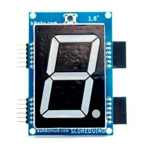
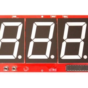
Scoreduino works with the following common anode seven segment display drivers. The seven-segment display drivers can be controlled by a Scoreduino Android app or RF remote control or the inbuilt switches.
All the drivers are designed for COMMON ANODE seven-segment displays. It can trigger these drivers:
- 1.2 inch RED common anode seven segment display driver– works with 5V-6V. Works with other colors also after changing resistors.
- 1.8 inch RED common anode seven segment display driver– works with 5V-6V. Works with other colors all after changing resistors
- 2.3 inch RED common anode seven segment display driver– works with 9V. Works with other colors also after changing resistors.
- 3 inch RED common anode seven segment display driver– Works with 12V. Works with other colors also after changing resistors.
- 4 inch RED common anode seven segment display driver– Works with 12V. Works with other colors also after changing resistors.
- 5 inch RED common anode seven segment display driver– Works with 15V. Works with other colors also after changing resistors.
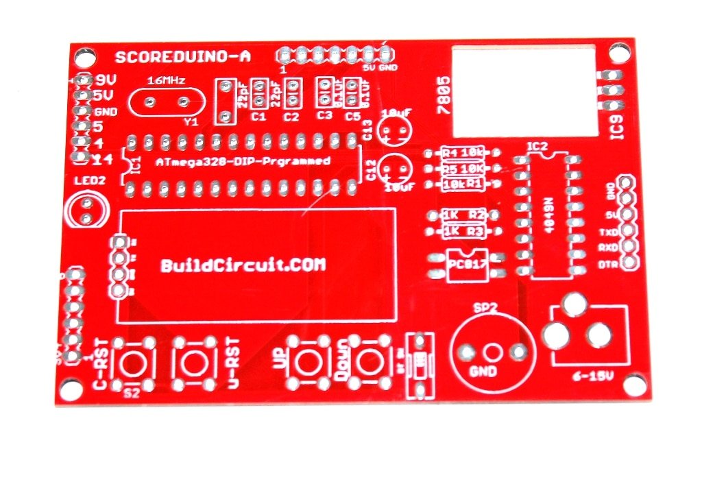
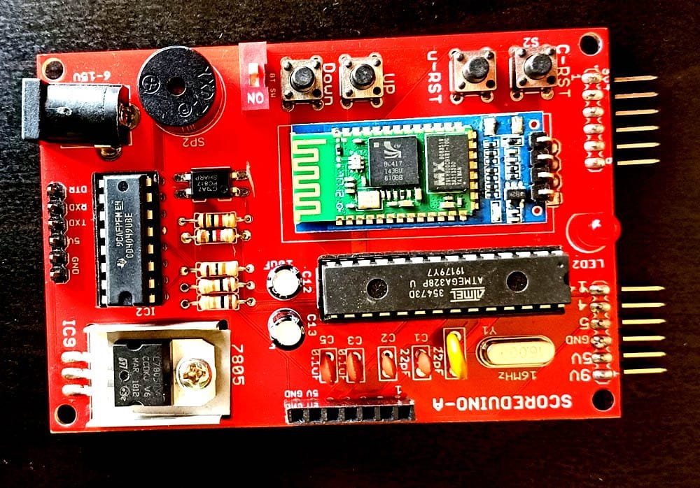
Components used:
- 1 x PCB
- 1 x Bluetooth module
- 1 x RF module
- 1 x FTDI basic
- 1 x 28 pin IC socket
- 1 x Atmega328P-PU with Arduino bootloader
- 4 x tactile switch
- 1 x 5mm LED
- 2 x 22pF
- 1 x 16Mhz oscillator
- 2 x 0.1uF capacitor
- 1 x 500mA resettable fuse
- 2 x 10uF capacitor
- 2 x 6 pin angle male header
- 1 x 6 pin male header for FTDI basic breakout board
- 1 x 1P DIP switch
- 1 x LM7805
- 1 x heat sink for LM7805
- 3 x 1K resistors
- 2 x 10K resistors
- 1 x PC817 optocoupler
- 1 x DC barrel
- 1 x buzzer
- 1 x 16 pin IC socket
- 1 x CD4049 chip
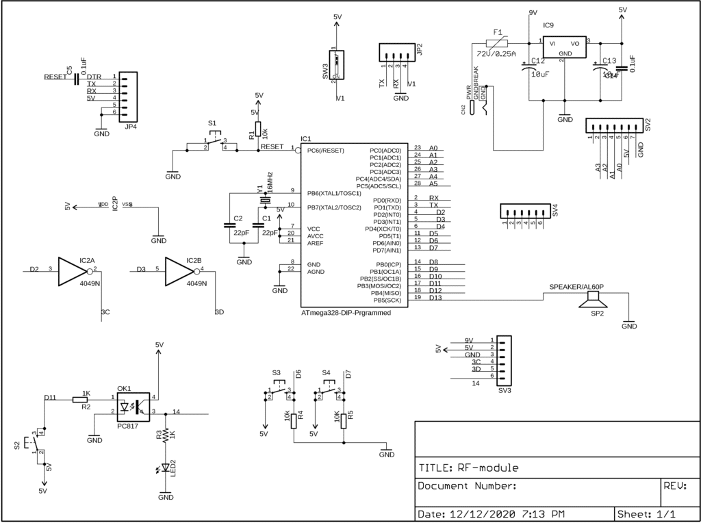
The Schematic:
It uses these two modules
 Dive into our collection of DIY Kits,
  Audio Amplifiers, Digital Scoreboards, FM transmitters, and more!
 Explore endless possibilities at our new store.

You may also like…
Related products
-
TSTR04 – 4 Channel Outputs 4 Temperature Sensors Wi-Fi Smartphone Relay (Thermostats)
Checkout in our STORE -

SCORE4- SCOREMICRO using Leonardo Pro Micro
Checkout in our STORE -

3 Inches SCORE5- Digital Scoreboard with 3″ and 2.3″ displays
Checkout in our STORE -
SCORE-C Basic Cricket Scoreboard With 2.3″ displays
Checkout in our STORE
