


Amarino shield 3.0 experiments- Android and Arduino
On this post, you will see how Amarino shield can be used for Android- Arduino experiments. It shows some basic experiments with android serial emulator and Amarino toolkit. You can get the original Amarino source codes and installable files also. Just install the application on your Android phone and experiment with the kit.
This page basically gives examples for using Amarino 3.0, but you can also use the same source codes for Amarino shields 1.0 and 2.0.
Circuit layout for Amarino 3.0 shield:

DIP switches are not shown in the circuit layout
Experiment 1: CD4094 basic experiment with Amarino 3.0 shield
This experiment has been derived from HEF4794_- Arduino_ Experiment.
This example makes the use of an LED Driver in order to control an almost endless amount of LEDs with only 4 arduino pins. We use the CD4094. Here, you can get the original version of this experiment:http://www.arduino.cc/en/Tutorial/LEDDriver . The Arduino team has used HEF4794.
An LED Driver has a shift register embedded that will take data in serial format and transfer it to parallel. It is possible to daisy chain this chip increasing the total amount of LEDs by 8 each time. You need to refer to datasheet for connecting more CD4094.
The code example you see here is taking a value stored in the variable dato and showing it as a decoded binary number. E.g. if dato is 1, only the first LED will light up; if dato is 255 all the LEDs will light up.
Experiment 1, Arduino sketch: Download
Experiment 2: Experiment with Android Serial Emulator, CD4094 and Arduino
Before you move on to this experiment, I recommend you to try Experiment 1.
For this experiment, you can use ANY KIND of Android emulator. Here are some examples of Android Serial Emulators.
I have used BLUE TERM. You can also search this application from your Android Phone.
Download source code of BLUE TERM: LINK 1 LINK 2 LINK3
Experiment steps:
Step 1: Download the BLUETERM application or any other general Bluetooth serial emulator for Android.
Step 2: DOWNLOAD ARDUINO SOURCE CODE and upload on your arduino.
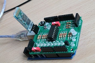
Step 3: Stack Amarino shield over your Arduino and connect the Bluetooth Adaptor.
Step 4: Connect your phone to Bluetooth adaptor via Serial Emulator.
Step 5: Press a number from 0 to 255, and press ? , you will see LEDs responding to binary form of that number.
For example, press 1? glows 1 LED, i.e. 1= 00000001
or 255? glows all LEDs, i.e. 255 = 11111111
or 3? glows 2 LEDs, i.e. 3 = 00000011
Video:
Amarino Experiments
Amarino page: http://www.amarino-toolkit.net/
(Note: The Arduino sketch for this experiment is slightly different from the original source codes from Amarino. The extra codes on the sketch deactivates the CD4094 chip. It is necessary to deactivate CD4094, because the power is shared with the chip and it affects your experiments. In Amarino 3.0 shield, you can use the IC1 switch (DIP) to switch off CD4094 while doing Amarino experiments.)
Some points that apply to all Amarino experiments:
– The Arduino Sketch has its baud rate set at 9600 bits/s. Therefore, your Bluetooth adapter should also have the same baud rate. Generally, the default baud rate of BlueSMiRF and general bluetooth adaptors is 9600 bps. However, if you want to change baud rate of BlueSMiRF module, follow this link. I have tested this experiment with both 57600 bps and 9600 bps and it works perfectly well. I don’t know if we can change baud rate of general Bluetooth adaptors.
Experiment 3: RGB Multicolor Lamp using Amarino
This experiment is similar to my previous tutorials on RGB multicolor lamp using Amarino. and RGB multicolor lamp with custom Bluetooth ID on Amarino Interface.
If you have never worked with Amarino, I strongly recommend you to visit Amarino page and understand the basics of Amarino.
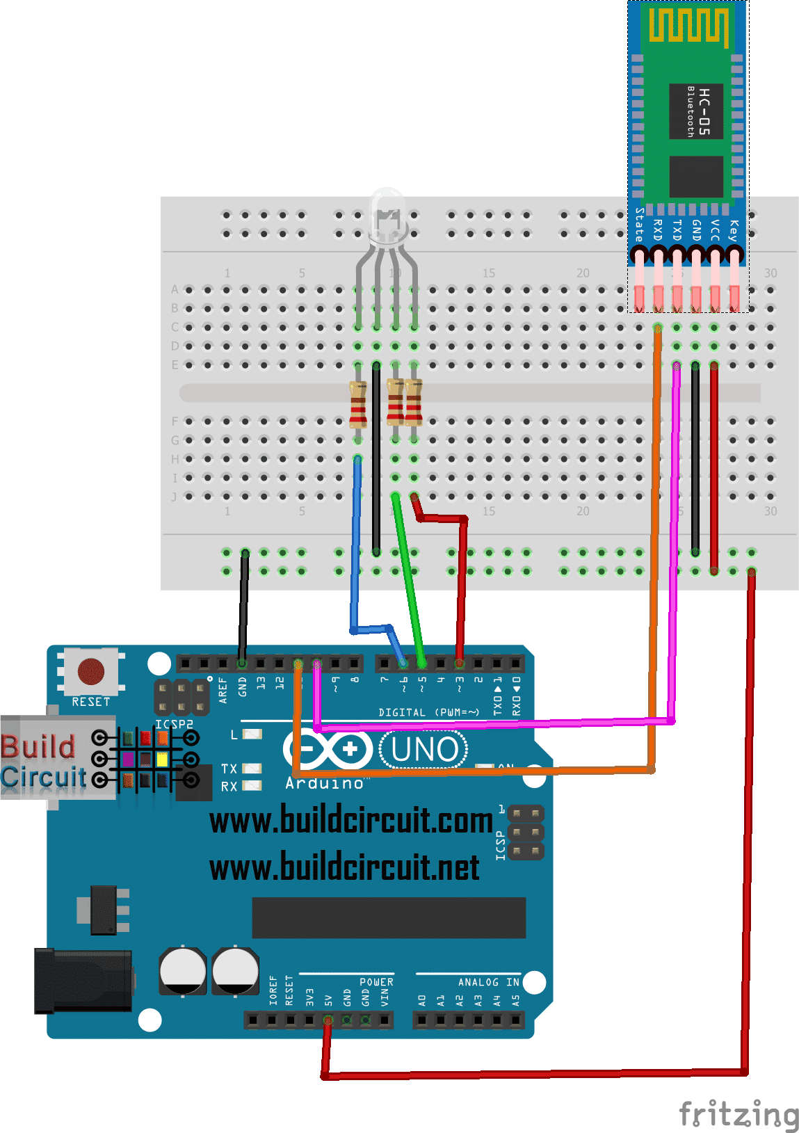
RGB LED connection to Arduino Shield:
We have used common cathode RGB LED for the Multicolor lamp experiment. The connections:
Red: Digital Pin 3
Green: Digital Pin 6
Blue: Digital Pin 5
Get the circuit layout of Android- Arduino DIY Shield
Steps:
a. Download Amarino and install on your Android Phone.
b. Download Amarino Library for Arduino and move it to the Libraries folder.
c. Download multicolor lamp application. and install on your phone. If you know Android Programming you candownload the Android source code also. You can also get original Amarino source code.
d. Download Arduino code for Multicolor Lamp and upload in your Arduino.
e. Stack your shield and Bluetooth adaptor over Arduino. Below you can see the connections for BlueSMiRF Mate Silver and general adaptor.
f. Activate Bluetooth function of your phone and note down the MAC ID of your Bluetooth adaptor and write it on the text box of your RGB Lamp application.
g. Connect to the Bluetooth adaptor from your phone and operate the RGB Lamp.
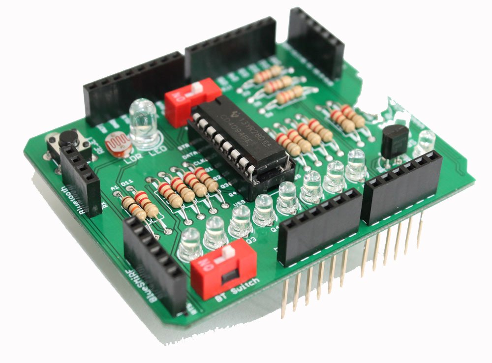
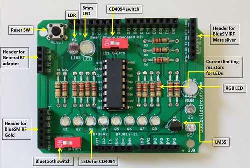
See photos of Amarino shield V.3.0.
Experiment 4: Sensor graph and LED controller using Amarino
This experiment is similar to my previous tutorials Sensor Graph basic experiment and Sensor graph and LED controller together.
If you have never worked with Amarino, I strongly recommend you to visit Amarino page and understand the basics of Amarino.
Connection: In this experiment, the sensor signal from LDR is fed to A1. You can also see A1 clearly on PCB.
Get the circuit layout of Smart Phone- Arduino Shield
Steps:
a. Download Amarino and install on your Android Phone.
b. Download Amarino Library for Arduino and move it to the Libraries folder.
c. Download sensor graph(with LED controller) application and install on your phone. If you know Android Programming you can download the Android source code also. You can also get original Amarino source code, the original source code has only the Sensor Graph interface.
d. Download Arduino code and upload in your Arduino.
e. Stack your shield and Bluetooth adaptor over Arduino. Below you can see the connections for BlueSMiRF Mate Silver and general adaptor.
f. Activate Bluetooth function of your phone and note down the MAC ID of your Bluetooth adaptor and write it on the text box of your application.
g. Connect to the Bluetooth adaptor from your phone and operate the LED and see the LDR sensor’s response on the Amarino interface.
Note: The LED and LDR have been kept together so that LED light falls properly on the LDR and you can see the light sensor response clearly on the graph. If your room is highly illuminated, you can put piece of paper for better results.
See photos of Amarino shield V.3.0.
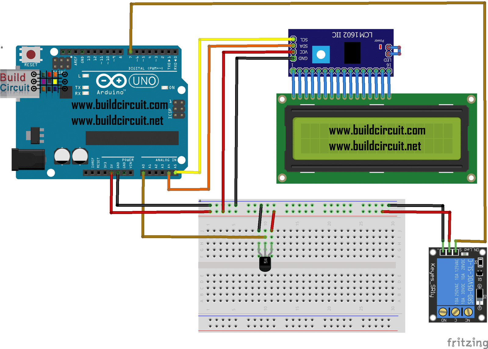
Experiment 5: Temperature sensor and LED controller using Amarino shield 3.0
This experiment is similar to my previous tutorial- Sensor graph and LED controller together.
You can also see one more similar experiment- Sensor graph and LED controller using Smart Phone- Arduino Shield.
If you have never worked with Amarino, I strongly recommend you to visit Amarino page and understand the basics of Amarino.
Connection: In this experiment, the sensor signal is fed to A0.
Get the circuit layout of Amarino Shield
Steps:
a. Download Amarino and install on your Android Phone.
b. Download Amarino Library for Arduino and move it to the Libraries folder.
c. Download temperature data(with LED controller) application and install on your phone. If you know Android Programming, you can download the Android source code also.
d. Download Arduino code and upload in your Arduino.
e. Stack your shield and Bluetooth adapter over Arduino. Below you can see the connections for BlueSMiRF Mate Silver and general adapter.
f. Activate Bluetooth function of your phone and note down the MAC ID of your Bluetooth adapter and write it on the text box of your application.
g. Connect to the Bluetooth adapter from your phone, operate the LED and see the LM35 temperature data on the Amarino interface.
See photos for Amarino shield V.3.0.
You can also modify this example to get the temperature data in graphical form.
Important points:
In Amarino shield version 3.0, there are spaces for 3 different bluetooth adapters.
a. General Bluetooth Adaptor – Cheapest adapter available on www.buildcircuit.net.
b. BlueSMiRF– Bluetooth Mate Silver– More expensive available on sparkfun.com.
c. BlueSMiRF Gold – The most expensive, available on sparkfun.com.
– Whichever Bluetooth adaptor you are using, the baud rate of Bluetooth adapter should match with the Serial Monitor’s baud rate. For example, if your Arduino source code has
Serial.begin(57600);
Then, the baud rate of Bluetooth adaptor should also be 57600. The default baud rate of BlueSMiRF module and general adaptor is 9600. The shield works excellent with 9600. However, if you want to change the baud rate of BlueSMiRF module, here’s a tutorial
I don’t know if we can change the baud rate of general Bluetooth adaptors with the above mentioned process, I have not tried it yet.
– This project has been tested with BlueSMiRF module as well as general Bluetooth Adaptor Module and it works well.
See photos for Amarino shield V.3.0.

🛠️ Dive into our collection of DIY Kits, 🔊 Audio Amplifiers, Digital Scoreboards, FM transmitters, and more!
🎶 Explore endless possibilities at our new store.

I want to build two bluetooth devices that act like switches.They connect with each other then the one is the transmitter and one the receiver. The transmitter can send commands to the receiver that can switch 10 lights on and off .