Assembly Guide- WTV020SD-16P evaluation board- DIY kit
This post shows you how to assemble the WTV020SD-16P evaluation board. You can get full description of this kit on this page.
The assembly process is straight forward. It can be easily assembled if you follow the silkscreen indicators(labels) and have beginning experience with a soldering iron. You will need to read the resistor bands or use a multimeter to determine the resistor sizes.
Kit includes:
- Bare PCB with silkscreen indicators.
- 4 x reset tactile switch
- 2 x 10uF electrolytic capacitors
- 2 x 0.1uF ceramic capacitors
- 1 x PTC resettable fuse
- 2 x 3mm LED
- 1 x DC barrel
- 1 x 500 Ohm variable resistor
- 1 x 1N4001 diode
- 1 x 3.3V regulator chip (L78L33)
- 1 x LM7805 (5V regulator chip)
- 1 x TO-220 heat sink for LM7805
- 1 x 4 pin male header
- 1 x 6 pin female header
- 2 x 8 pin female headers for stacking the music module
- 1 x 470R resistor
- 1 x 330R resistor
You need would other components that are not included along with the kit package and you need to buy those separately.
Buy these components separately:
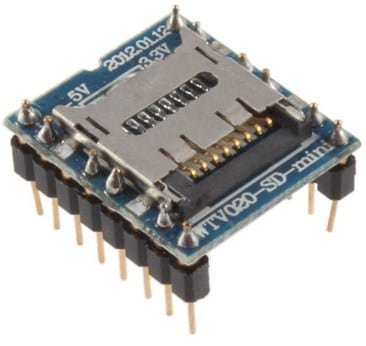
- WTV020SD-16P music module
- 2GB MicroSD card
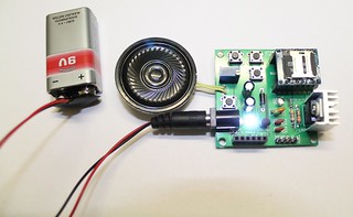
- 8 Ohm- 0.25W- Thin Speaker
- Audio amplifier module (optional)
You can get full description of this kit on this page.
Now, you can start the assembly process. We have skipped some steps on this post. If you want to see all the steps, please check this tutorial.
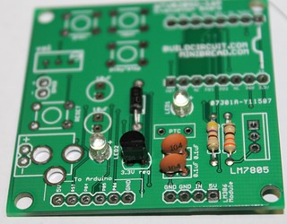
Step 1: Solder resistors 330R and 470R.
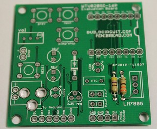
Step 2: Solder 2 pcs 0.1uF ceramic capacitors, 3mm LEDs, 3.3V regulator and 1N4001 diode.
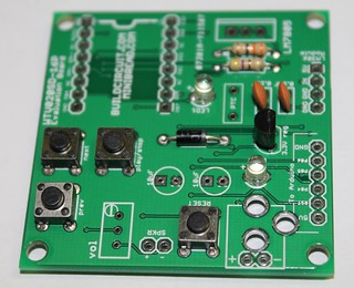
Step 4: Solder all the tactile switches.
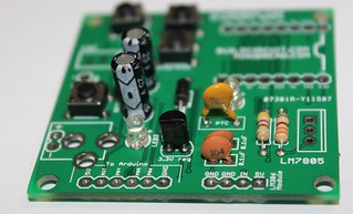
Step 5: Solder 2 pcs 10uF capacitors and 300mA resettable PTC fuse.
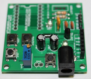
Step 6: Solder 500 Ohm variable resistor. The image shows 103 (which is 10K) which is incorrect. We send you 500 Ohm variable resistor.
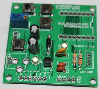
Step 7: Solder DC barrel, 6 pin female header and 4 pin male header
Step 8: Connect a 8 Ohm speaker and solder 2pcs of 8 pin female header for stacking the WTV020SD module.
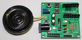
Step 9: Solder LM7805 regulator chip.
Step 10: Stack WTV020-16P music module over the female headers. Your evaluation kit for wtv020sd module is ready. Simply, power the board with a 6-9V power supply and play AD4 format music files.
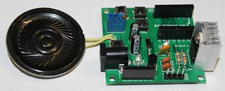
Optional:
You can connect an LM386 based audio amplifier to the kit. The amplifier will amplify the audio for you.
Click here to watch the video of the kit with the audio amplifier connected.
Output video:
Related documents:
🛠️ Dive into our collection of DIY Kits, 🔊 Audio Amplifiers, Digital Scoreboards, FM transmitters, and more!
🎶 Explore endless possibilities at our new store.