Multivibrator
A multivibrator is an electronic circuit used to implement a variety of simple two-state systems such as light
emitting diodes, timers and flip-flops.
🛠️ Dive into our collection of DIY Kits, 🔊 Audio Amplifiers, Digital Scoreboards, FM transmitters, and more!
🎶 Explore endless possibilities at our new store.

A multivibrator is an electronic circuit used to implement a variety of simple two-state systems such as light
emitting diodes, timers and flip-flops.

Remote tester circuit also resembles the logic of a “dark sensor (using BC557)”. LDR has been replaced with IR sensor TSOP 1738. The circuit works as a remote tester. Pressing a remote control switch near the IR sensor, switches on the LED D2.

This 555 timer circuit below toggles the LED when a button is pressed. Pins 2 and 6, the threshold and trigger inputs, are held at 1/2 the supply voltage by the two 10K resistors.

This circuit has been configured in Astable mode. The output pulses are determined by the values of resistors R1, R2 and the timing capacitor C1. The formula for the frequency of pulses is: f= 1.44/[(R1+2R2)*C1].
The high and low time of each pulse can also be calculated.

Monostable mode of operation
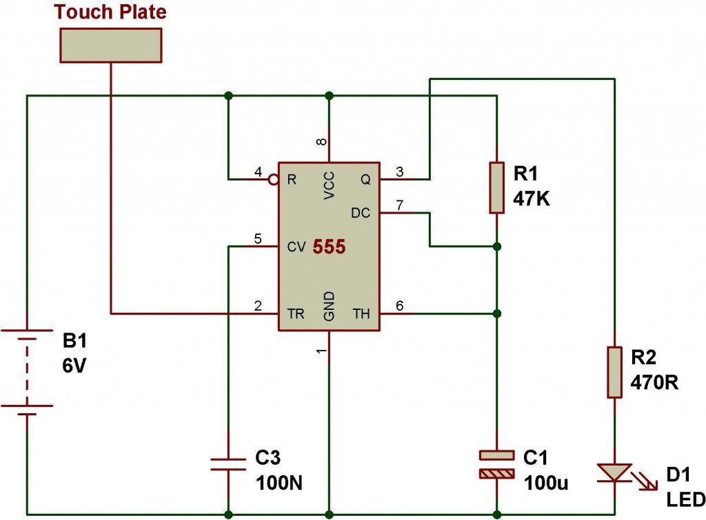
Monostable mode of operation of 555 IC can be explained using a simple touch sensitive circuit. Here, timing constant (T) of monostable timer= 1.1*R1*C1. The following circuit has been configured in monostable mode. A monostable circuit produces a single pulse(for a certain duration determined by the Timing Constant(T)=1.1*R1*C1) when triggered at pin 2.


A breadboard is a device for testing temporary electronics projects. Components used to test a circuit can be reused for other projects. None of the components are damaged.
Almost all people start to learn electronics using breadboard because it is the simplest way of making circuit. The photograph shows a typical small breadboard which is suitable for beginners building simple circuits with one or two ICs (chips).

Automatic Light detector using variable resistor
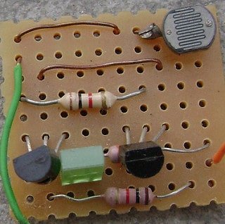
A light detector senses light. As the light level increases and LDR meets the lowest threshold resistance, the circuit automatically turns on the LED D1. We can adjust the sensitivity using the preset VR1-10K.
LESS RESISTANCE(VR1)-> LESS DARKNESS TO SWITCH OFF THE LED
HIGH RESISTANCE(VR1)-> MORE DARKNESS TO SWITCH OFF THE LED

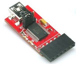
Description: This is a basic breakout board for the FTDI FT232RL USB to serial IC. The pinout of this board matches the FTDI cable to work with official Arduino and cloned 5V Arduino boards. It can also be used for general serial applications. The major difference with this board is that it brings out the…