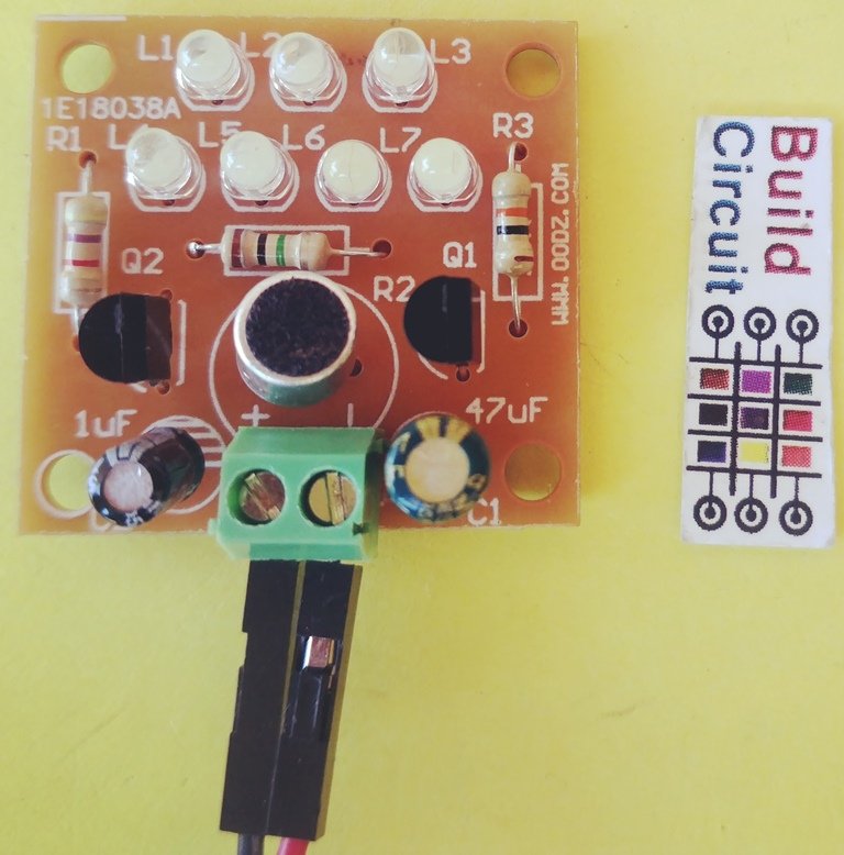
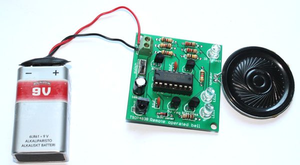
This is a very basic electronic DIY kit for electronics beginners. There are few LEDs in the circuit that can be turned on by sound. The larger the sound intensity the more the LEDs glow. There is a microphone in the circuit which is sensitive enough to pick surrounding sounds.
When music or other sounds are heard, the LED lights will flicker with the rhythm of the sound(sound speed).
Working Voltage:
3-4.5V. If you need a higher working voltage, you can add current limiting resistance to the LED.
Circuit principle:
1. The sound control LED light circuit consists of a power circuit, microphone amplifier circuit and LED light indicator circuit.
2. The power supply input is from JP, and C1 filter power supply path is used. The small
electret microphone converts the sound signal into an electrical signal.
3. The electrical signal is coupled through C2 to Q2 and amplified.
4. The amplified signal is then sent to Q1 base. Q1 will initiate the LED to flicker. The louder the sound, the higher the LED brightness.
Soldering tips:
2. When assembling, use a shearing resistance foot to solder to the two electrodes of the microphone and then assemble it on the circuit board.
3. The power supply point has positive and negative marks, and the power supply is usually connected with the dupont wires. It can also be connected directly from the battery box of 3-4.5 V.
The schematic of the kit is shown below:

Check out all the images below for assembly tips. You can also see these images on Flickr.
Other images of the kit
🛠️ Dive into our collection of DIY Kits, 🔊 Audio Amplifiers, Digital Scoreboards, FM transmitters, and more!
🎶 Explore endless possibilities at our new store.
