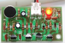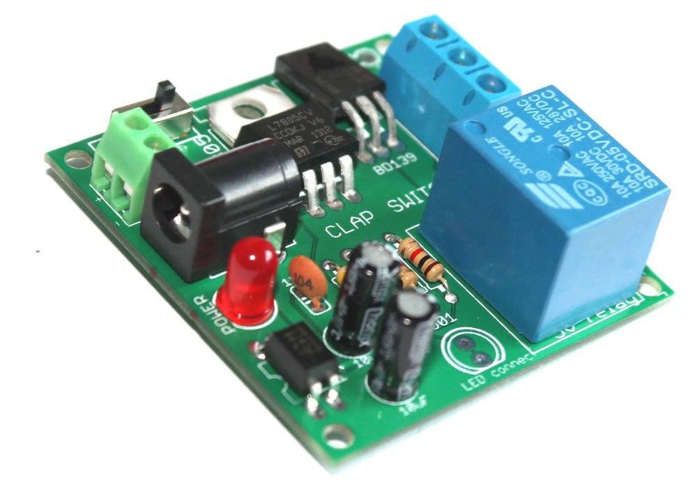
Fully assembled clap switch for 100-220V AC light bulbs

DIY CLAP SWITCH

This fully assembled sound/clap operated switch can be used for turning on your 100-240V AC light bulbs. Usually, we use a clap switch to operate a lamp and it can easily do that for you. The kit responses to clap up to distance of 5 meters, but, the further you go, the louder the clap should be.  (more…)

How to use the fully assembled clap switch

DIY CLAP SWITCH

We are now selling fully assembled CLAP SWITCH(shipped from Sydney, Australia). Click here to visit the product page. 

If you have come to this page from a search engine, we recommend you to visit the page about DIY clap switch. In this article, we are going to describe how you can use the “do-it-yourself(DIY) clap switch” to light up 100-240V appliances. When we say 100-240V appliance used with a clap switch, it is usually a bulb/lamp/CFL(Compact Fluorescent Lamp) tube. This article is for absolute beginners, so, we will try to explain all the small details. (more…)

Do-it-yourself (DIY) clap switch for 100-220V AC appliances

DIY CLAP SWITCH

This do-it-yourself(DIY) sound/clap operated switch can be used for switching your 100-240V AC electrical appliances. Usually, we use a clap switch to operate a lamp and it can easily do that for you. The kit responses to clap up to distance of 10 meters, but, the further you go, the louder the clap should be.  (more…)

About relay module for clap switch- operate 100-240V appliance

connecting a lamp

Description: This is a dependent DIY kit module that has to be used with a clap_switch available at buildcircuit.net. This kit DOES NOT work independently as a clap switch. It is useless without this_clap_switch_kit. So, you need to order that kit also.

You can read about the clap-switch at this link.

clap-switch-diy-kit

The relay module is operated by this clap switch

 Buy now button

The relay module comes as a pack of parts kit and is easily assembled if you can follow the silkscreen indicators (labels) and have beginning experience with a soldering iron. You will need to read the resistor bands or use a multimeter to determine the resistor sizes. Both the kits operate with 9V batteries.

Step 10- Solder 5V relay and your kit is ready for blog

Features:

  • A DIY kit module that works with this_clap_switch_kit. It is useless without the clap switch.
  • >Operates a 100-240V lamp with clap/loud sound.
  • Supply voltage: 6V-9V. The same power supply can be used for this_clap_switch_kit.
  • There are two supply input points: a DC barrel and a screw terminal. You can use one of the points to power up the kit.
  • Dimension: 48.26mm x 49.53mm.
  • Relay specification: Activation voltage: 5V DC. Controls appliances operating at 10A 250VAC, 10A 125VAC, 10A 30VDC, 10A 28VDC. Suitable for Europe, North America, Australia and New Zealand.

Schematic of relay module:

Click on the image to enlarge it.

schematic relay module for clap switch

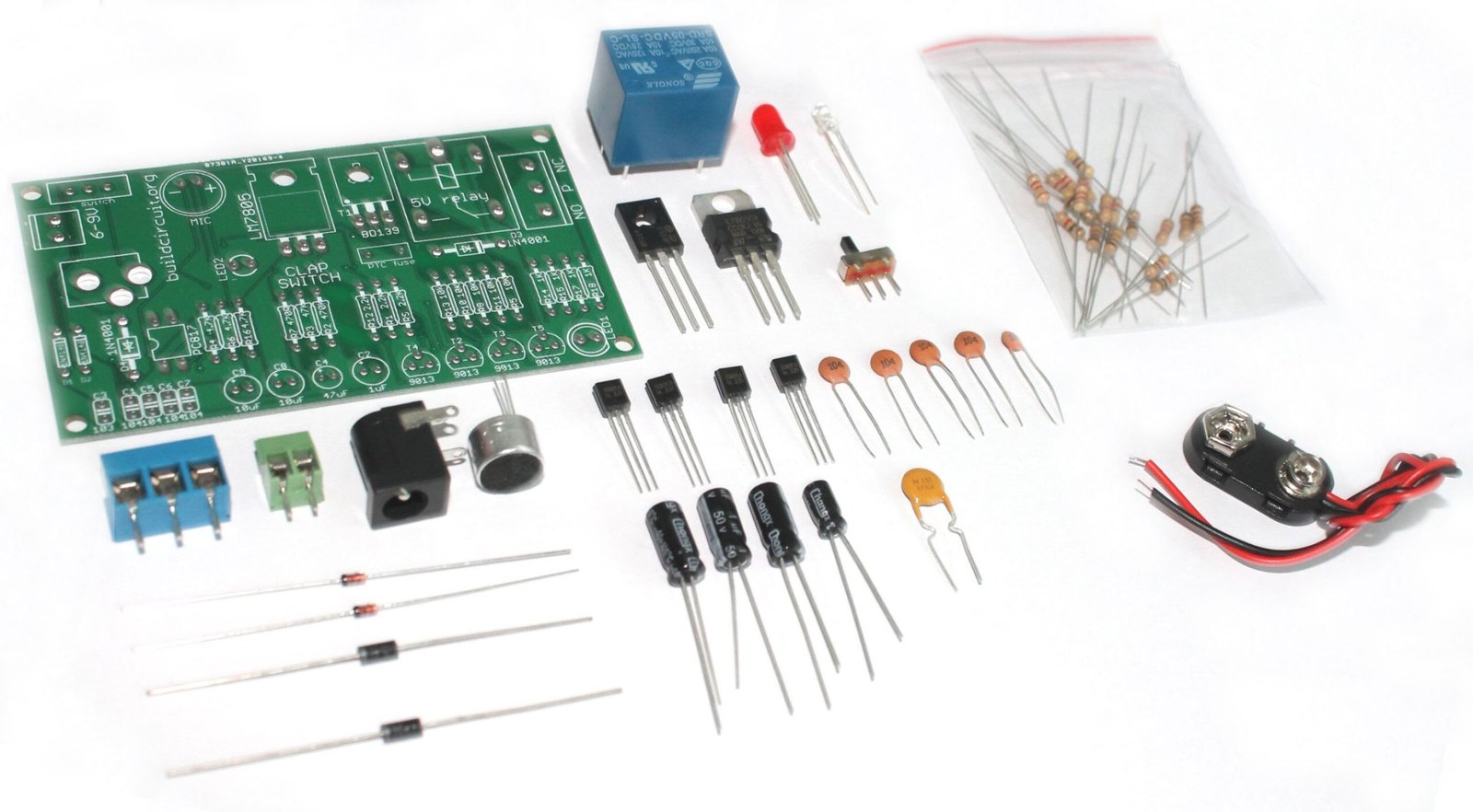
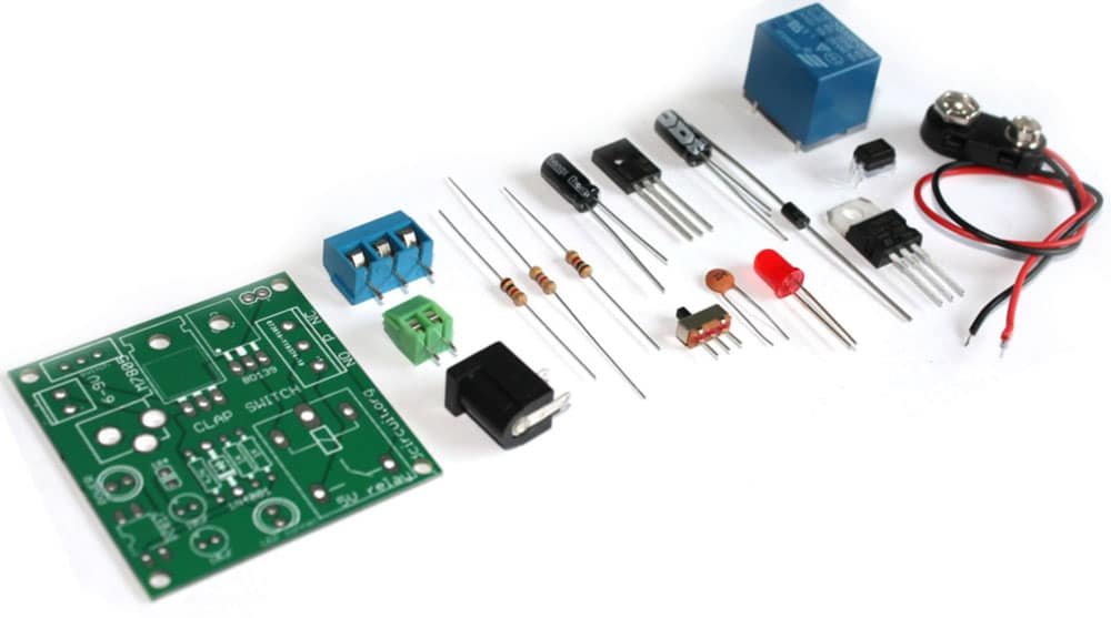
The kit package contains the following components:

  1. 1 x Bare PCB with Silkscreen indicators
  2. 2 x 1K carbon film resistor
  3. 1 x 4.7K carbon film resistor
  4. 1 x 1N4001 diode
  5. 1 x LM7805
  6. 1 x BD139
  7. 1 x 0.1uF (code- 104)
  8. 2 x 10uF capacitor
  9. 1 x PC817 optocoupler
  10. 1 x SPDT switch
  11. 1 x 5V relay
  12. 1 x 3 pin screw terminal
  13. 1 x 2 pin screw terminal
  14. 1 x DC barrel
  15. 1 x 5mm LED
  16. 1 x 9V battery connector

Buy now button

Documents:

Video:

How to connect the relay module to the popular clap switch


connecting a lamp

This article strictly focuses on how to connect the relay-module to the popular clap-switch. If you have come to this page from a search engine, we recommend you to visit the following pages:

1. About Relay module for the popular clap_switch (Get description of this kit)

2. How to connect clap-switch to the relay module

3. How to use the relay-module and the clap-switch to operate electrical appliances

Please follow the shown steps:

Step 1: Connect the cathode point of clap-switch to the cathode of relay-module.

Step 1- connect the cathode pin of clap switch kit to the anode pin of relay module

Step 2: Connect the anode point to anode point.

Step 2- Connect the anode pin of clap switch kit to the anode pin of relay module

Step 3: Connect the JST connector of clap-switch module to the relay-module. The clap-switch module gets power from the relay-module.

Step 3- Connect the black(negative) wire of clap switch to -ve pin on the board and do the same for the red (positive) wire also

Step 4: Connect a 9V battery to power up the kits. The clap-switch module gets power from the relay-module.

The connection between the kits is ready

Step 5: This is how you connect the lamp to the combination of kits. 

connecting a lamp


This kit is available at our online store www.buildcircuit.net.

Step 10- Solder 5V relay and your kit is ready

Buy now button


Video:

Recommended documents:

Assembly tutorial- Relay module DIY kit for popular clap switch

connecting a lamp

In this article, we have described how you can assemble your relay module for the popular clap-switch. If you have come to this page from a search engine, we recommend you to visit the following pages:

Related articles:

1. About Relay module for the popular clap_switch (Get description of this kit)

2. How to connect clap-switch to the relay module

3. How to use the relay-module and the clap-switch to operate electrical appliances

You can see the following steps to make your relay module for the popular clap-switch.

PCB

Step 1: Solder 2pcs of 1K resistor and 4.7K resistor

Step 1- Solder 4.7K and 1K resistors

Step 2: Solder 1N4001 diode

Step 2- Solder 1N4001 diode

Step 3: Solder LM7805 voltage regulator and BD139 transistor

Step 3- Solder LM7805 and BD139

Step 4: Solder 0.1uF capacitor

Step 4- Solder 0.1uF capacitor

Step 5: Solder PC817 optocoupler

Step 5- Solder PC817 optocoupler

Step 6: Solder SPDT switch and 2 pin screw terminal

Step 6- solder SPDT switch and 2 pin screw terminal

Step 7: Solder 5mm LED. This works as power indicator

Step 7- Solder 5mm LED for power indicator

Step 8: Solder DC barrel for connecting power supply.

Step 8- Solder DC barrel and 2pcs 10uF capacitors

Step 9: Solder 3 pin screw terminal

Step 9- Solder 3 pin screw terminal

Step 10: Solder 5V relay

Step 10- Solder 5V relay and your kit is ready

Step 11: Connect the cathode point of clap switch module to the cathode point of relay module

Step 1- connect the cathode pin of clap switch kit to the anode pin of relay module

Step 12: Connect anode point of clap switch module to the anode point of relay module

Step 2- Connect the anode pin of clap switch kit to the anode pin of relay module

Step 13: Connect the JST connector of relay module to the + and – point on the clap switch module. The clap switch module gets power from the relay module.

Step 3- Connect the black(negative) wire of clap switch to -ve pin on the board and do the same for the red (positive) wire also 

Step 14: Connect a 6-9V battery to the kit and connect electrical lamp.

The connection between the kits is ready

NOTE: We are selling a slightly different PCB, this will make your job easier. This is better than the previous one. Available in BLUE color. See the image below to know how you can connect the relay module to the clap switch

CLICK HERE to see all the steps- How to connect a lamp to the relay module

Step 15: The following image shows how you can connect a lamp to the relay module

connecting a lamp

Buy now button

Documents:

Video:

How to connect a lamp to DIY relay module for the popular clap switch

The connection between the kits is ready

If you have come to this page from a search engine, we recommend you to visit the following pages:

1. About Relay module for the popular clap_switch (Get description of this kit)

2. How to connect clap-switch to the relay module

3. How to use the relay-module and the clap-switch to operate electrical appliances

In this article, we are going to describe how you can use the “clap_switch module+relay_module” to light up 100-240V appliances. When we say 100-240V appliance used with a clap switch, it is usually a bulb/lamp/CFL(Compact Fluorescent Lamp) tube. This article is for absolute beginners, so, we will try to explain all the small details. (more…)

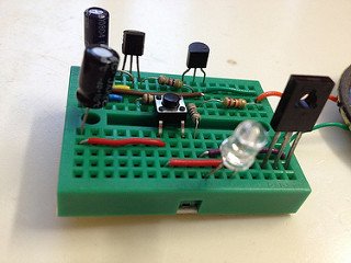
Build a simple DIY clap switch

Description: Here’s a simple DIY clap switch circuit. The circuit is mainly composed of an audio frequency and a bistable trigger circuit.

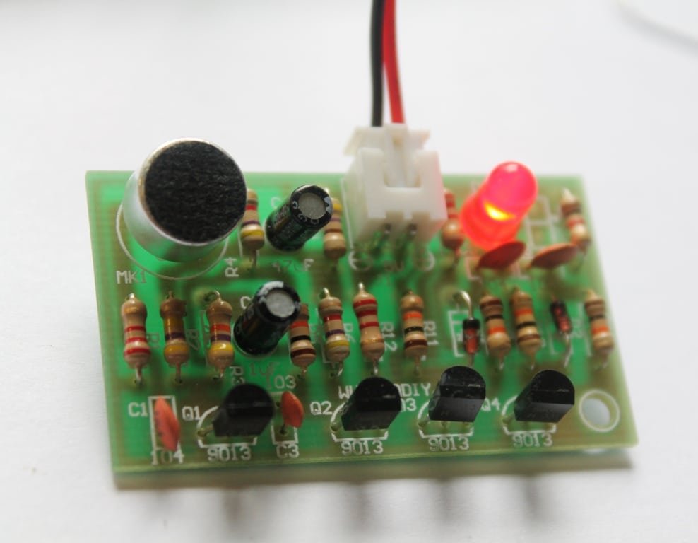
Q1 and Q2 together form an amplifier circuit. MK1 (electret microphone) accepts Clap/Audio signal and that enters to transistor Q1 through the coupling capacitor C1 and enters to Q2 base through collector directly after getting amplified. And it obtains a negative square-wave which used to trigger the bistable circuit from Q2’s collector.  (more…)

Simplest DIY clap switch- Assembly tutorial

If you have come to this page from a search engine, please check this article to know about clap switch. Follow the given steps to assemble the DIY clap switch.

Step 1:Collect all the required components for assembling the kit.

STEP 1

 Step 2: Read and confirm the specifications of the components.

STEP 2

Step 3: Insert all the resistors in its respective place according to its specifications.

sTEP 3

Step 4: Insert the ceramic capacitors into the board according to its labelled  specification.

STEP 4

Step 5: Insert the diode in its respective place.

STEP 5

Step 6: Insert the four transistors in the board.

STEP 6

Step 7: Place electrolytic capacitors according to its specification.

STEP 7

Step 8: Insert mic and LED into its place in the circuit board.

STEP 8

Step 9: Connect 2 pin JST connector in the circuit.

STEP 9

Step 10: Clap switch in action.

STEP 12

Video:

BC-216

100-240V AC Light Bulb Controllable FULLY Assembled Clap Switch

£11.04
This FULLY ASSEMBLED sound/clap operated switch can be

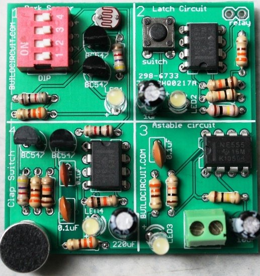
4 in 1 DIY kit- dark sensor, latch circuit, astable multivibrator and clap switch

This is a simple 4-in-1 do-it-yourself (DIY) kit from BuildCircuit. The kit has four different circuits that can be switched on separately or together at a time using a DIP switch.

The four circuits are:

1. Dark sensor using LDR.

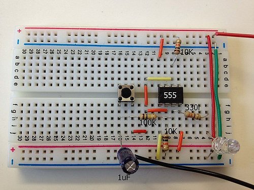
2. A latch circuit using NE555 timer.

3. Astable circuit using NE555 timer.

4. A clap-switch circuit using NE555 timer.

Besides these 4 circuits, by changing the values of the resistors and capacitors, you can change the behaviour of the circuits. (more…)

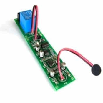
SOUND ACTIVATED SWITCH – RELAY

This project is a sound-activated switch.

DESCRIPTION

Clap switch/Sound-activated switch designed around op-amp, flip-flop, and popular 555 IC. Switch avoids false triggering by using a 2-clap sound. Clapping sound is received by a microphone, the microphone changes the sound wave to an electrical wave which is further amplified by the op-amp.

555 timer IC acts as a mono-stable multi-vibrator then flip-flop changes the state of the output relay on every two-clap sound. This can be used to turn ON/OFF lights and fans. The circuit activates upon a two-clap sound and stays activated until another sound triggers the circuit.

Specifications:

  • Supply 12V DC @ 60mA
  • On board preset to set the sensitivity
  • On board LED to indicate the Relay on/off state
  • On board Microphone
  • Relay switch 5Amps, 110V-230V

SCHEMATIC

Sound_Activated_Switch_Top_schematic

PARTS LIST

image description

PCB

buildcircuit.com

Search products (DIY Kits, Arduino, Modules, Sensors, Components and Gadgets)

New Products

Popular Products

BC-3014A

3 Digit Digital Objects Counter With Laser Module

£11.83£15.79
This is 3 digits digital object counter kit
BC002

LCD Shield For Arduino-Bluetooth Android Hobbyists

£9.46
This LCD shield is designed for experimenters who
BC-44654

Arduino based Bluetooth tester module with 12 ports

£9.46
  • Basic Arduino based module for Android-Arduino communication.

Recent Posts

What is a voltage divider circuit

A voltage divider network is a fundamental electronic circuit used to divide a voltage into smaller fractions. It consists of two or more resistors connected in series or in a string, which create intermediate voltage points between the supply voltage and ground. Voltage dividers are commonly used for various purposes in electronics, including setting reference […]

Factors affecting Wi-Fi transmission range

The range of a Wi-Fi signal can be influenced by several factors, which can impact its coverage and strength. Understanding these factors can help you optimize your Wi-Fi network for better performance. Here are the key factors that affect Wi-Fi transmission range: Frequency Band: Wi-Fi operates in different frequency bands, such as 2.4 GHz and […]

Factors affecting Bluetooth transmission range

Bluetooth technology has become an integral part of our wireless communication landscape, enabling a wide range of devices to connect and exchange data. However, the transmission range of Bluetooth connections can vary based on several factors. Here are some key factors that affect Bluetooth transmission range: Bluetooth Version: Different Bluetooth versions offer varying ranges. The […]

Unveiling the Power of Open Source Hardware: A Collaborative Innovation Frontier

Introduction In an era characterized by rapid technological advancements and a growing emphasis on collaboration, open source principles have transcended the realm of software and made an indelible mark on hardware development. Open source hardware (OSH) represents a paradigm shift in innovation, fostering a community-driven approach that democratizes access to technology and enables a more […]

Arduino Projects

Arduino Projects AllArduino Arduino project 60- Arduino based thermostat and relay August 1, 2019 Arduino Project 59- Digital voltmeter measuring from 0 to 30V August 1, 2019 Arduino Project 58- Infrared controlled robot car August 1, 2019 Arduino project 57- Obstacle avoiding robot using Arduino August 1, 2019 Arduino Project 52- Parking sensor using ultrasonic […]

Basic Introduction to NextDFM software

CONTACTLESS AUTOMATIC WARDROBE LED LIGHT WITH FADE EFFECT

Contact-less controlled automatic wardrobe light turns on the LED when you open the wardrobe door. Τhe project is based on Hall effect IC including LED driver and tiny magnet. Board doesn’t require any mechanical switch. When magnet is close to the board, LED is off, when you open the wardrobe door magnet goes far from […]

LUX METER MODULE

LUX Meter project has been design to measure the illumination.  Illumination is luminous flux falling on surface area of photo diode.  This illumination converted to corresponding voltage using Op-Amp circuit. SPECIFICATIONS Supply 9 VDC PP3 Battery @ 20 mA  Onboard Photo Diode  Onboard preset for calibration  Range selection via jumper 10mV/LUX, 1mV/LUX, 0.1mV/LUX  Interfacing is […]

5 beginners projects that work in the first attempt

Just started electronics ? And you don’t know any engineering behind your projects and you are afraid of failure ? Then, this article can help you get started in electronics.

Usually, success in initial projects plays important role in electronics amateurs and engineering students’ career. Many students quit electronics because they fail in their first, second projects. After few failures, student keep a misconception that electronic projects working now might not work later. Thus, I recommend beginners to start with those projects which will work in their first attempt and give inspiration from your own work.

(more…)

Super Easy Electronics Projects for Absolute Beginners

There are hundreds of electronics projects published on buildcircuit.com. This time we have selected few projects that should be easier for beginners to start with. Complex and difficult projects just frustrate the beginners. The best thing about the listed projects is that all come with good assembly images and most of the projects can be made with 5-10 components.  The components used for one project can be used for other projects also.
(more…)

Search for products

Back to Top
Product has been added to your cart