Up Counter
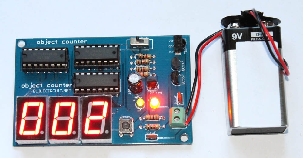
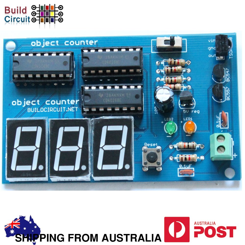
An up counter simply counts from 0 to 9. We can use this circuit to make digital object counter. This circuit can also be used to make a digital clock.
Digital Object Counter using LDR and digital IC
555 timer configured in monostable mode is a simple automatic dark sensor circuit that gives output when light falling on LDR is blocked.
Basic RC circuit
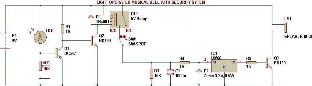
For the circuit to work as light operated musical bell, we need to connect the SW1- switch to N/C terminal of relay. LDR has to be kept in a dark case.
FM transmitter and Dark sensor
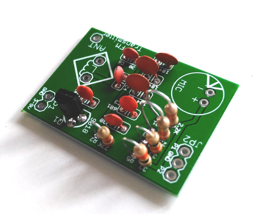
A dark sensor can be converted to a simple FM transmitter using the following components. This FM transmitter is very sensitive and it has transmitting range of 30 meters.
Telephone misuse indicator
When the phone line is in idle condition (on hook), the full voltage of 48V DC from the exchange appears across the line. When the phone is engaged by lifting the hand set, the voltage across the line falls down to around 12V. Thus, under idle condition (48V), VR1 is adjusted to give a positive biasing voltage to the base of Q3. As Q3 conducts Q1 gets into reverse bias and stops conduction. If the phone is engaged, Q3 stops conducting due to voltage drop across the lines, and subsequently, Q1 and Q2 starts oscillating and beeping is heard. Thus, this circuit can be used as an indicator for telephone tapping and misuse by an unauthorized person.
Dark sensor using BC557
An automatic dark sensor can be made using a PNP transistor(BC557).
AM receiver from dark sensor
In this case, LDR has been replaced with capacitor C1-0.01uF and resistor R3-1K has been replaced with L1 & VC1. In place of a LED, a Piezo Diaphragm has been kept.
We just need to add inductor, capacitor and a piezo diaphragm to convert a dark detector to an AM radio.
Mode of NE555- Astable
This circuit has been configured in Astable mode. The output pulses are determined by the values of resistors R1, R2 and the timing capacitor C1. The formula for the frequency of pulses is: f= 1.44/[(R1+2R2)*C1].
Sound generator and Musical toy organ
One of the main objectives of LDR Engineering projects is to make students capable of developing their own logic for making devices. Here is an example that tells how LDR Engineering helps in developing ideas.
How to use variable resistors
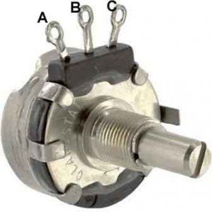
There are 3 pins/terminals on a preset. The maximum resistance that a preset can provide is written on it. If 100K is written on preset, it means that we can vary its resistance from 0 Ohm to 100K. A movable metal is rotated in clockwise or anticlockwise direction that changes the resistance of preset.
OR-gate realization
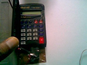
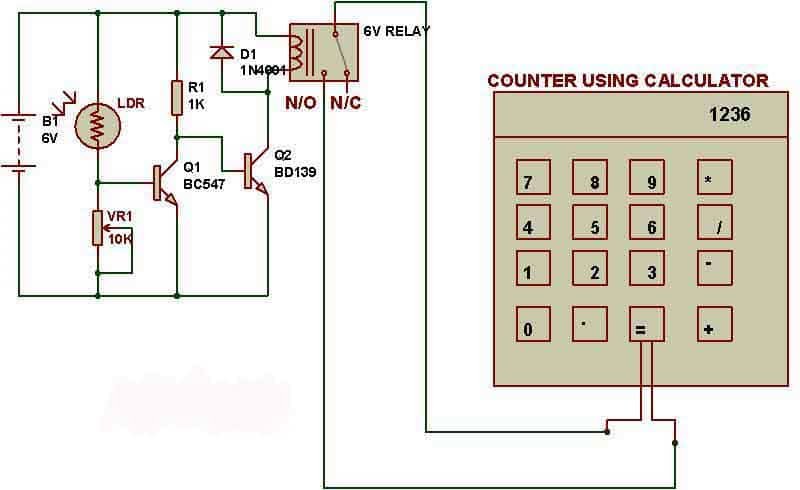
To make an object counter we can use a simple dark detector circuit and a normal calculator. Pole and NO (Normally Open) terminals of a relay have to be connected to the two pins which are used to activate ‘=’ key of calculator.
As we block the light falling on LDR, the calculator starts counting.
For the calculator to work as a counter, we first need to press ‘1’ and ‘+’ keys.
Object counter using LDR and calculator
To make an object counter we can use a simple dark detector circuit and a normal calculator. Pole and NO (Normally Open) terminals of a relay have to be connected to the two pins which are used to activate ‘=’ key of calculator.
As we block the light falling on LDR, the calculator starts counting.
For the calculator to work as a counter, we first need to press ‘1’ and ‘+’ keys.
Water Level Indicator
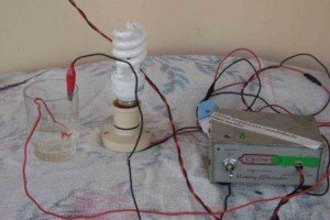
We can use the logic of making an automatic light detector to make a simple water level indicator.We just need to remove LDR from the circuit and put the wires into water, then it simply works as water level indicator. There is a specific resistance between the wires that are dipped into water and conduction of electricity through water gives biasing voltage to base of transistor.
The sensitivity can be adjusted using VR1. Put 470K variable resistance in VR1.
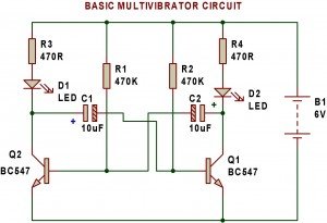
Multivibrator
A multivibrator is an electronic circuit used to implement a variety of simple two-state systems such as light
emitting diodes, timers and flip-flops.
Remote Tester
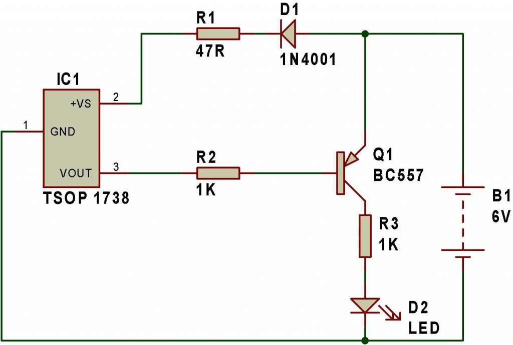
Remote tester circuit also resembles the logic of a “dark sensor (using BC557)”. LDR has been replaced with IR sensor TSOP 1738. The circuit works as a remote tester. Pressing a remote control switch near the IR sensor, switches on the LED D2.
Toggle switch
This 555 timer circuit below toggles the LED when a button is pressed. Pins 2 and 6, the threshold and trigger inputs, are held at 1/2 the supply voltage by the two 10K resistors.
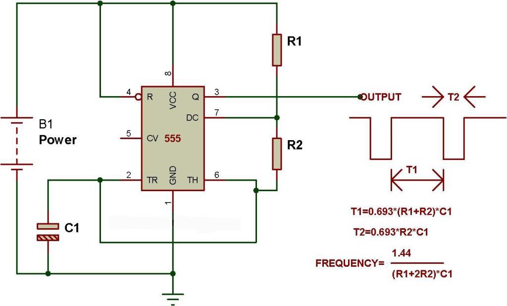
Mode of NE555- Astable
This circuit has been configured in Astable mode. The output pulses are determined by the values of resistors R1, R2 and the timing capacitor C1. The formula for the frequency of pulses is: f= 1.44/[(R1+2R2)*C1].
The high and low time of each pulse can also be calculated.
Mode of NE555- Monostable
Monostable mode of operation
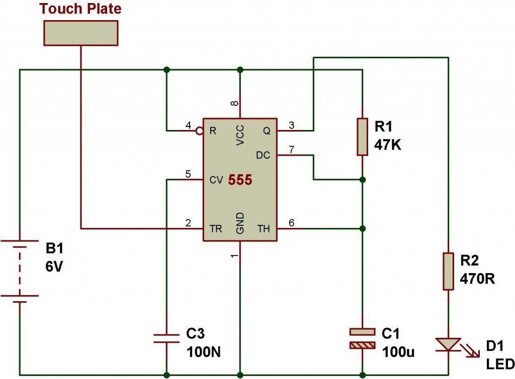
Monostable mode of operation of 555 IC can be explained using a simple touch sensitive circuit. Here, timing constant (T) of monostable timer= 1.1*R1*C1. The following circuit has been configured in monostable mode. A monostable circuit produces a single pulse(for a certain duration determined by the Timing Constant(T)=1.1*R1*C1) when triggered at pin 2.