


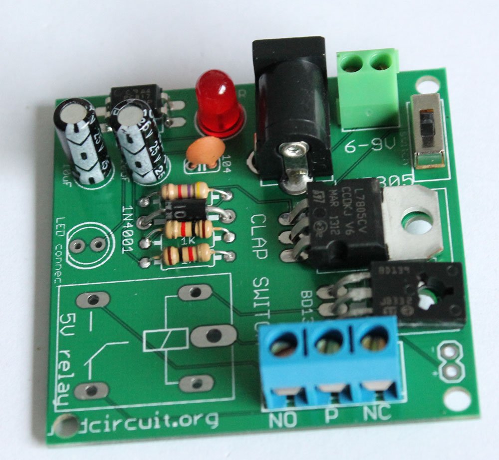
Assembly tutorial- Relay module DIY kit for popular clap switch
In this article, we have described how you can assemble your relay module for the popular clap-switch. If you have come to this page from a search engine, we recommend you to visit the following pages:
Related articles:
1. About Relay module for the popular clap_switch (Get description of this kit)
2. How to connect clap-switch to the relay module
3. How to use the relay-module and the clap-switch to operate electrical appliances
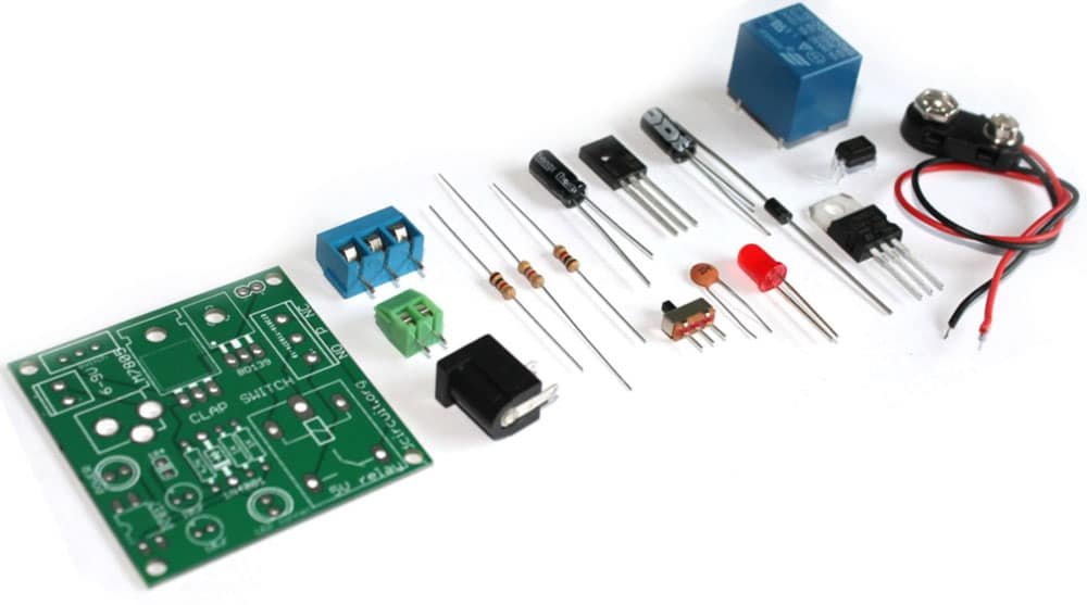
You can see the following steps to make your relay module for the popular clap-switch.
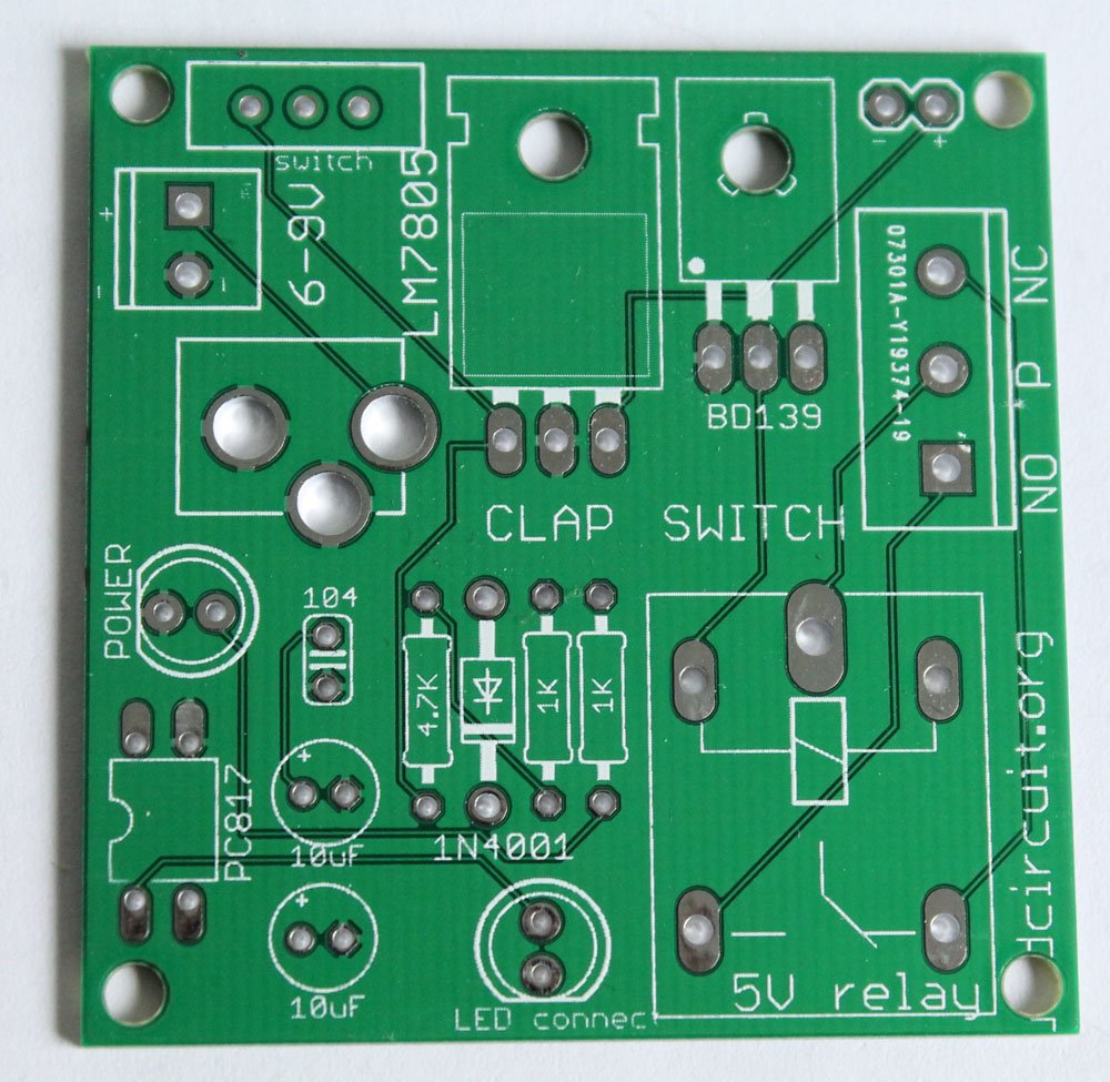
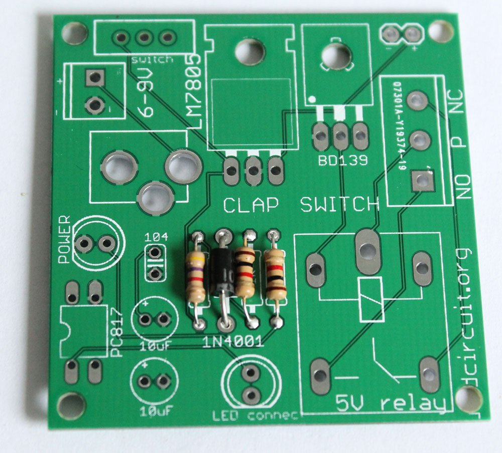
Step 1: Solder 2pcs of 1K resistor and 4.7K resistor

Step 2: Solder 1N4001 diode
Step 3: Solder LM7805 voltage regulator and BD139 transistor

Step 4: Solder 0.1uF capacitor

Step 5: Solder PC817 optocoupler

Step 6: Solder SPDT switch and 2 pin screw terminal

Step 7: Solder 5mm LED. This works as power indicator

Step 8: Solder DC barrel for connecting power supply.

Step 9: Solder 3 pin screw terminal
Step 10: Solder 5V relay

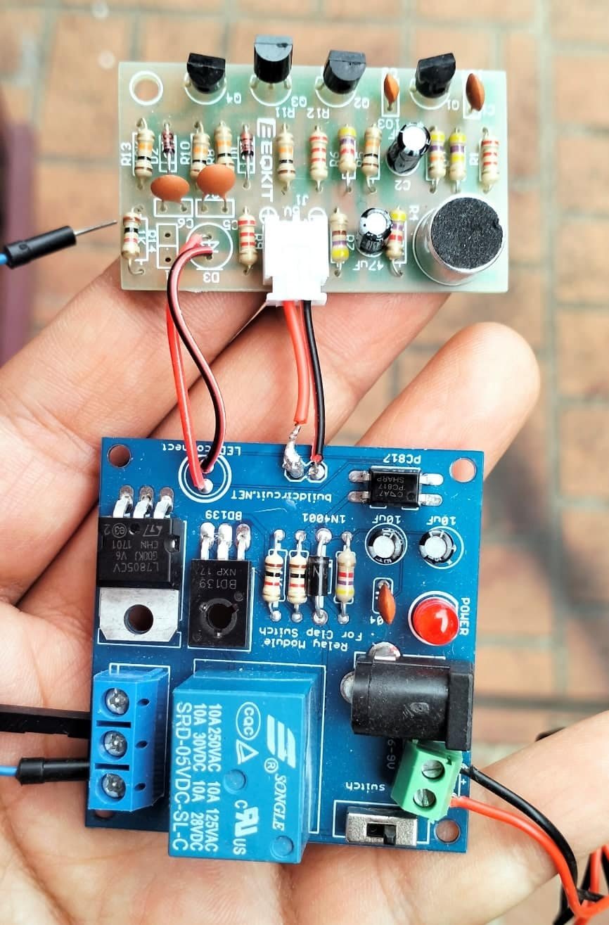
Step 11: Connect the cathode point of clap switch module to the cathode point of relay module
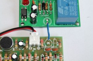
Step 12: Connect anode point of clap switch module to the anode point of relay module
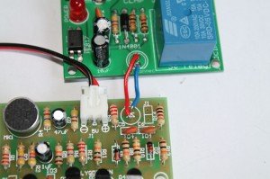
Step 13: Connect the JST connector of relay module to the + and – point on the clap switch module. The clap switch module gets power from the relay module.

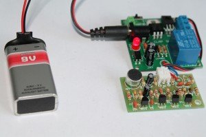
Step 14: Connect a 6-9V battery to the kit and connect electrical lamp.
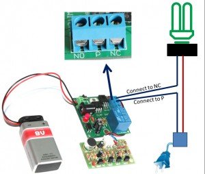
NOTE: We are selling a slightly different PCB, this will make your job easier. This is better than the previous one. Available in BLUE color. See the image below to know how you can connect the relay module to the clap switch
CLICK HERE to see all the steps- How to connect a lamp to the relay module
Step 15: The following image shows how you can connect a lamp to the relay module
![]()
Documents:
- About relay-module
- Download all the images at once
- Other clap switch products at BuildCircuit Store
- How to use a relay
- Buy the kit
- Flickr Images
- About relay_module for clap-switch
- Assembly tutorial
- Connecting clap-switch to the relay-module
- How to connect a lamp to the relay-module
Video:
![]()
🛠️ Dive into our collection of DIY Kits, 🔊 Audio Amplifiers, Digital Scoreboards, FM transmitters, and more!
🎶 Explore endless possibilities at our new store.


